Download
1 / 31
320 likes | 471 Vues
4D Sensors: Unifying the Space and Time Domain with Ultra-Fast Silicon Detectors UFSD.

E N D
4D Sensors: Unifying the Space and Time Domain with Ultra-Fast Silicon Detectors UFSD Hartmut F.W. Sadrozinski withMarta Baselga, Nicolo Cartiglia, Scott Ely, VitaliyFadeyev, Zachary Galloway, Jeffrey Ngo, Colin Parker, Davi Schumacher, Abe Seiden, AndriyZatserklyaniySCIPP, Univ. of California Santa Cruz
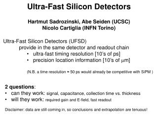
“4D” • Ultra-Fast Silicon Detectors (UFSD) incorporate the time-domain into the excellent position resolution of semiconductor sensors • They provide in the same detector and readout chain • ultra-fast timing resolution [10’s of ps] • precision location information [10’s of mm] A crucial element for UFSD is the charge multiplication in silicon sensors investigated by RD50, which permits the use of very thin detectors without loss of signal-to-noise. Hartmut Sadrozinski, “Exploring charge multiplication for fast timing with silicon sensors”, 20th RD50 Workshop, May 30 to June 2, 2012, Bari, Italy https://indico.cern.ch/getFile.py/access?contribId=18&sessionId=8&resId=1&materialId=slides&confId=175330 Hartmut F.-W. Sadrozinski, UFSD, HSTD9 Hiroshima Sep 2013
“4D” • We “just” need 3 items: • Charge Multiplication • Thin segmented sensors • Fast readout • 2 questions need to be addressed for UFSD: • can they work: signal, capacitance, collection time vs. thickness • will they work: required gain and E-field, fast readout • In this talk: • Charge collection in thin sensors • Low-Gain Avalanche Detectors (LGAD) • Charge multiplication data on pad detectors • Estimation of Time resolution • Motivation Hartmut F.-W. Sadrozinski, UFSD, HSTD9 Hiroshima Sep 2013
Collection of Charges in Silicon Sensors Drift velocity saturates for both electrons and holes! -> need thin sensors for fast charge collection Collection time is close to minimum when E-Field ≥ 20 kV/cm For 300um Si Collection time ~ 5 ns (h), ~ 3 ns (e) For 10um Si Collection time ~ 0.3 ns (h), ~ 0.1 ns (e) Hartmut F.-W. Sadrozinski, UFSD, HSTD9 Hiroshima Sep 2013
Details of Collected Charge in Thin Sensors Energy loss measurement for charged particles in very thin silicon layers S. Meroli, D. Passeri and L. Servoli 11 JINST 6 P06013 • Charge yield per um • for very thin silicon sensors:: • Reduced measured MPV • Increased relative dispersion • (see later) Hartmut F.-W. Sadrozinski, UFSD, HSTD9 Hiroshima Sep 2013
Can 4D-UFSD work? Correct Collected Charge Realistic gain & cap Good time resolution Collection time = thickness/vsat (vsat = 80 mm/ns) (holes) For pixel thickness > 5 um, Capacitance to the backplane Cb< Cint (200 fF) For pixel thickness = 2 um, Cb ~ ½ of Cint, and we might need bipolar (SiGe)? Viable sensor thickness 2 µm – 10 µm (i.e. 20-100 ps) Needed Gain: 4 – 25 for pixels, 20- 150 for 1 mm strips (much less than APD’s or SiPM) Note: CNM (Barcelona) and HLL (Munich) have been producing ~10 µm thick sensors. Hartmut F.-W. Sadrozinski, UFSD, HSTD9 Hiroshima Sep 2013
Charge Multiplication A. Macchiolo,16th RD50 Workshop Barcelona, Spain, May 2010 Charge multiplication in path length ℓ : At the breakdown field in Si of 270kV/cm: ae≈0.7 pair/µm ah ≈ 0.1 pair/µm → gain g = 33 possibleinl = 5 µm. → In the linear mode (gain ~10), consider electrons only Need to raise E-field as close to breakdown field as possible for high gain but not too much to prevent breakdown! Hartmut F.-W. Sadrozinski, UFSD, HSTD9 Hiroshima Sep 2013
Development of Si sensors with gain (RD50) See Giulio Pelligrini’s talk RD50 Groups have been investigating charge multiplication (CM) in heavily irradiated silicon sensors. Un-irradiated sensors manufactured without drastic changes to the doping profile exhibit very little gain before breakdown. RD50 Common Project to manufacture Low-Gain Avalanche Detectors (LGAD) based on the prinicple of SiPM or APD, but with moderate gain. Principle: Deep n-implants and extra p-layer increase the E-field so that moderatecharge multiplication occurs without breakdown. Gain > 104 Digital response • CNM Barcelona • First step: Pad detectors/simple diodes • verify gain, • optimize parameters • radiation hardness • Second step: strip/pixel sensors Hartmut F.-W. Sadrozinski, UFSD, HSTD9 Hiroshima Sep 2013
Low-Gain Avalanche Detector (LGAD) High-Field: Gain Marta Baselga, Trento Workshop Feb. 2013 Hartmut F.-W. Sadrozinski, UFSD, HSTD9 Hiroshima Sep 2013
Gain with MIP’s Hartmut F.-W. Sadrozinski, UFSD, HSTD9 Hiroshima Sep 2013
Charge Collection with a’s from Am(241) Am(241) illuminating the back side, range ~ few um’s “electron injection” signal drifts and is then amplified in high field a’s Colin Parker Fast signals! Observed rise times ≈ 400 ps allowing time-resolved current transient (TCT) analysis . Don’t know yet where the lower limit is, since we are still improving the BW of the system. Hartmut F.-W. Sadrozinski, UFSD, HSTD9 Hiroshima Sep 2013
Observed TCT shapes froma’s Total collection time = Σ of drift times of primary e’s and of h’s from multiplication Hartmut F.-W. Sadrozinski, UFSD, HSTD9 Hiroshima Sep 2013
Estimation of Gain with aTCT Total Gain = IM(a) / I(a)*DTM/DT~5*2=10 (N.B.: For thin sensors, both DTM and DT are shortened) Hartmut F.-W. Sadrozinski, UFSD, HSTD9 Hiroshima Sep 2013
From pads to strips and pixels New CNM production (RD50) 14 p-type wafers Thick Resistivity Substrate Substrate (µm) (Ωcm) resistivity (Ωcm) thickness (µm) 9.8 110.5 0.006 525 50.4 96.7 0.006 525 75.2 104.6 0.006 525 285 (FZ) 12000 ± 7000 Width/Pitch varies from 0.3 to 0.8 Hartmut F.-W. Sadrozinski, UFSD, HSTD9 Hiroshima Sep 2013
Fast Rise Time Sensors for Timing Why thin sensors for fast timing? Thin sensors allow fast rise time because of the fast collection time. But their S/N is reduced. Why not use thick sensors, and collect only the early part of the electrons or integrate the charge over longer time, reduce noise and trigger low on the rising pulse, like in LHC pixel sensors? In general: induced pulse development is fairly complicated (i.e. bipolar pulses in neighboring strips, possibility of increased “cross-talk”) so shaping at the collection time seems to be a safe thing to do. Time resolution due to noise and time walk (amplitude dispersion of Landau): Assume pulse of amplitude A with dispersionDA,electronic noisesAand rise time : f*A = For fast shaping, thin sensors: amplitude , for ≤ 8ns, f = 0.16 – 0.4 Hartmut F.-W. Sadrozinski, UFSD, HSTD9 Hiroshima Sep 2013
Time Resolution vs. Rise Time & Gain Assumes S/N =100 @ 20ns shaping like at LHC (before gain) Shaping time dependence of noise : 1/√t A gain of 10 (100) results in a time resolution of ~100 (30) ps Improvement of noise -> thinner sensors Improvement of time walk -> thicker sensors Hopefully Angelo Rivetti will tell us how to improve on this with a Constant-Fraction-Discrimunator CFD Stay tuned for pulse and SPICE simulations. Hartmut F.-W. Sadrozinski, UFSD, HSTD9 Hiroshima Sep 2013
CERN fixed-target experiment (NA62) needs very fast pixel sensors: Gigatracker (GTK) Prototype CFD system (INFN Torino) has ~ 100 ps resolution, predicted to be 30 ps in next iteration. Optimized for 200mm sensors and hole collection, could it be re-designed for electron collection from 2 – 10mm sensors? How realistic is Ultra-fast Readout? Time Walk: CFD Noise and Power: Si-Ge? Hartmut F.-W. Sadrozinski, UFSD, HSTD9 Hiroshima Sep 2013
Example of ASIC development for fast signal processing: Here much larger dynamic range Hartmut F.-W. Sadrozinski, UFSD, HSTD9 Hiroshima Sep 2013
4D Sensors: Unifying the Space and Time Domain with Ultra-Fast Silicon Detectors UFSD Sensor Production: CNM Barcelona Sensor Testing: UC Santa Cruz, Freiburg U., Florence U., SJI Ljublejana, Trento U. Readout ASIC: INFN Torino, UC Santa Cruz, Data Acquisition DAQ: HEPHY Vienna
Conclusions Timing precision in silicon sensors has been the Cinderella (before meeting the prince) of instrumentation, in contrast to photon detectors. (Sherwood Parker has been the only voice in the wilderness). With Ultra-Fast Silicon Detectors we want to reach the same happy ending as the fairy tale! We made quite a lot of progress in one year: Charge Multiplication Achieved gain 10 -15 with pad detectors Thin segmented sensors Received 10 um – 75 um epi strips/pixels Fast readout Area of next big push Hartmut F.-W. Sadrozinski, UFSD, HSTD9 Hiroshima Sep 2013
Acknowledgments This work was carried out in the framework of RD50 Common Projects and funded by the US Dept. of Energy. Special thanks to GiulioPellegrini and Salvador Hidalgo (CNM) for expert design and production of LGAD, and GregorKramberger for expert CCE and TCT measurements. Thanks to Harris Kagan for telling me over and over again that Silicon is not perfect, and to Abe Seiden and Nicolo Cartiglia for asking me if that can be true.. Hartmut F.-W. Sadrozinski, UFSD, HSTD9 Hiroshima Sep 2013
More Applications for 4D UFSD Hartmut F.-W. Sadrozinski, UFSD, HSTD9 Hiroshima Sep 2013
Thin 4D Sensors Sensor ASIC Thinned FZ sensors with “ribs” for strength (HLL-MPI, CNM): even photons Position and Energy Position and Time Counter Chip Epitaxial sensors Ideal for prototyping Hartmut F.-W. Sadrozinski, UFSD, HSTD9 Hiroshima Sep 2013
Up to now, semiconductor sensors have supplied precision data only for the 3 space dimensions (diodes, strips, pixels, even “3D”), while the time dimension has had limited accuracy (e.g. to match the beam structure in the accelerator). We believe that being able to resolve the time dimension with ps accuracy would open up completely new applications not limited to HEP An example in HEP are forward physics projects at the LHC, like the AFP. Scattered protons are tracked from stations 100’s of meters downstream back to the interaction region and the z-vertex is determined from the timing information. A time resolution of 10ps results in a resolution in the vertex resolution of 3 mm. 4D sensors can give the required good resolution both in position resolution and timing in one sensor, while at the moment two different detector technologies are required (e.g. pixels and Micro-channel plates). Proposal: Combined-function pixel detector will collect electrons from thin n-on-p pixel sensors read out with short shaping time electronics. 4D sensors rely on internal charge multiplication to increase the collected signal Motivation for 4D Detectors Hartmut F.-W. Sadrozinski, UFSD, HSTD9 Hiroshima Sep 2013
Benefits of Ultra-Fast Silicon Detectors - Tracking: Identifying with high precision the temporal signature of different events allows for their association and it reduces random coincidences. Traditional tracking is often overwhelmed by combinatorial backgrounds, which can be dramatically reduced by adding a 4th dimension (time) per point. - Vertex Locator: Forward physics in AFP (ATLAS) and HRS (CMS) - Time of Flight (ToF): ToF is already used in many commercial applications such as ToF-enhanced PET and Mass Spectroscopy ToF, however with precision one order of magnitude higher than the goal of UFSD (~500 ps vs. ~50 ps). ToF is also used in particle physics as a tool for particle identification. - ToF can also be used in 3D and Robotic Vision: the ability to accurately measure the travel time of light pulses reflected by an object at unknown distance is of paramount importance to reconstruct 3D images, fundamental in imaging and robotic vision. UFSD will offer a spatial precision of a few mm at low illumination power, allowing for battery operated, portable systems. - Particle counting: UFSDperformance would allow developing new tools in single particle counting applications with unprecedented rate capabilities. For example, in the treatment of cancer using hadron beams, such a tool would measure the delivered dose to patients by directly counting the number of hadrons. Material science experiments using soft x-rays will benefit from the combination of high rate and precision location that UFSDoffers. Hartmut F.-W. Sadrozinski, UFSD, HSTD9 Hiroshima Sep 2013
Charge multiplication (CM) in silicon sensors (investigated by RD50 institutions) can have much wider applications then off-setting charge lost due to trapping during the drift of electrons or holes in irradiated sensors. • Charge multiplication makes silicon sensors similar to drift chambers (DC) or Gas Micro-strip Detectors (GMSD), where a modest number of created charges drift to the sense wire, are amplified there (by factors of > 104) and are then used for fast timing. • Recall our experience with DC: • Need to balance the need of high E-field around a wire to have charge multiplication with the need to keep the E-field low to prevent breakdown (wire diameter, field shaping wires,.) and give proper drift field. • The drifting electrons contribute mainly to the collected charge after they have undergone charge multiplication, which means that the pulse develops (in principle) in a short time. • The very large charge density in the “plasma cloud” prevents the electron to move until the ions have drifted away! So electron signal is given by hole dynamics!? • Basic question for use of CM • What field strength do we need? • Can the sensor geometry and doping profile engineered so that the amplification field can be kept high, but just below the breakdown field? Internal Gain in Detectors
Time of Flight for Particle Identification in Space. The Alpha Magnetic Spectrometer (AMS) detector, operating in the International Space Station since 2011, performs precision measurements of cosmic ray composition and flux. The momentum of the particles is measured with high-resolution silicon sensors inside a magnetic field of about 1 m length. Atime resolution of 10 picoseconds, the “Holy Grail” of Cosmic Ray Physics: the distinction between anti-carbon ions and anti-protons can be achieved up to a momentum of 200 GeV/c. Hartmut F.-W. Sadrozinski, UFSD, HSTD9 Hiroshima Sep 2013
Future: 4-D Ultra-Fast Si Detectors in pCT Protons of 200 MeV have a range of ~ 30 cm in plastic scintillator. The straggling limits the WEPL resolution. Replace calorimeter/range counter by TOF: Light-weight, combine tracking with WEPL determination Range straggling limit for 200 MeV p Hartmut F.-W. Sadrozinski, UFSD, HSTD9 Hiroshima Sep 2013
Positron Emission Tomography PET Study accumulation of radioactive tracers in specific organs. The tracer has radioactive positron decay, and the positron annihilates within a short Distance with emission of 511 keVγ pair, which are observed in coincidence. Perfect Picture: Resolution and S/N Effects: Resolution of detector (pitch) Positron range A-collinearity Parallax (depth) T: true event S: Compton Scatter R: Random Coincidence A. Del Guerra, RESMDD12 Hartmut F.-W. Sadrozinski, UFSD, HSTD9 Hiroshima Sep 2013
Reduce Accidentals & Improve Image: TOF-PET PET t1 t2 TOF-PET Localization uncertainty: Dd= c x Dt /2 When Dt = 200 ps ➔Dd = 3 cm @ VCI K. Yamamoto 2012 IEEE NSS-MIC Hartmut F.-W. Sadrozinski, UFSD, HSTD9 Hiroshima Sep 2013
ToF – PET SNR Improvement • The improved source localization due to timing • leads to an improvement in signal-to-noise • and an increase in Noise Equivalent Count NEC For a given acquisition time and dose to the patient, TOF can provide better image quality and improved lesion detection. OR with TOF the scan time and dose can be reduced while keeping the same image quality ( better clinical workflow and added comfort for the patient). 600 ps -> 30 ps 20x Dose reduction M. Conti, Eur. J. Nucl. Med. MoI Imaging (2011) 38:1147-1157 • Photon Timing improvement is a major R&D Field Hartmut F.-W. Sadrozinski, UFSD, HSTD9 Hiroshima Sep 2013