Download

1 / 39
390 likes | 511 Vues
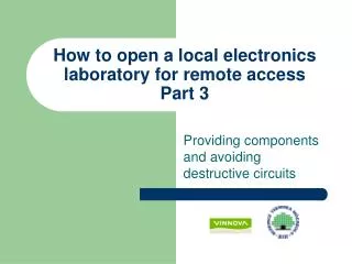
How to open a local electronics laboratory for remote access Part 4. Providing components and avoiding destructive circuits. Outline. Providing physical components for remote experimenters Assuring that it is only possible to create harmless circuits Advanced experiments Summary.

E N D
How to open a local electronics laboratory for remote accessPart 4 Providing components and avoiding destructive circuits
Outline • Providing physical components for remote experimenters • Assuring that it is only possible to create harmless circuits • Advanced experiments • Summary
Component handling and circuit checking in a local laboratory • The instructor puts a set of components to be used in the lab session on each workbench • During the session the students are permitted to activate the sources in their circuits only when the instructor have checked that the circuits are harmless
VISIR Laboratory - Providing components • As in the traditional laboratory the user is provided with a set of components needed for the experiment • These will be available on the breadboard in the lab client • The component set is prepared in advance by the teacher
Checking circuits • Before constructing the circuit in the switching matrix it is checked by the Virtual Instructor to ensure that it is safe • The Virtual Instructor is configured with descriptions of “safe circuits”
Laboratory Configuration • Experiments requires different components • These requirements are often described in the lab instruction manual • Components to support the experiments are mounted in the switching matrix • Descriptions of “safe circuits” are provided to the Virtual Instructor
From Circuit to Matrix Virtual Instructor • Circuit is wired on the virtual breadboard • Circuit is checked by the Virtual Instructor • If the circuit is safe it is allowed to be constructed in the switching matrix
Cards in the Matrix Component board Osc. board DMM board Source board
Components used in lab exercises are installed in the matrix Components for the students
Matrix board Node A Node X1 Relay NR Node I Type, NR and Version
Matrix board Socket for Multi-lead Components Components Socket
Mounting a component Connection to Node A Component Connection to Node B
Describing the component • All components that are mounted in the matrix are described in a component list • The resistor would be described as: R_2_7 A B 10k
Component Description • Type • R, L, C, OP, etc • Card and Relay Number • Refers to the exact position in the matrix • Nodes • Depending on the type the number of nodes can vary • Value • Component value, 10k, 10mH, 1uF, etc
Multiple relays • One component may need many relays • As is the case with components with more than two leads • Described by using sequence of card and relay numbers separated by : (colon sign) • X_1_1:1_2:1_3
An excerpt from the Component List OP_4_10:4_11:4_13 NC B D G NC C F NC uA741 The OP component type has 8 connectors, of which pin 1,5 and 8 are not connected in this example. The component value is uA471. Because of the many connectors several relays must be used to connect them all to the operational amplifier. All of them will close when the component is in use.
Source board Relays to connect FGENA Type, NR and Version Relays to connect Power
Source board functions • Connects the function generator to node A • Lower terminal hardwired to 0 VFGENA_24_1 A 0 • Connects the channels of the power supply to the bus • +/-25V is relative to COM • +6V is relative to 0 The source board usually has card number 24
Connecting the power supply • Extended nodes used:
From bus to node • From the extended node, the power supply node can be wired to the node needed for the experiment, by using a jumper on a component board. • VDC+25V_24_4:4_5 F • The source board with card number 24, relay 4, will connect the +25V channel to the X2 bus node. • A jumper has been installed on card 4, relay 5. Connecting X2 to F.
The source connections are listed in the Component List Excerpt from the Component List:* Power supply VDC+6V_24_3 : 4_7 A VDC+25V_24_4:4_5 FVDC+25V_24_4:4_3 DVDC-25V_24_5:4_4 GVDCCOM_24_2 0 Source board Component board
DMM Card Low Side High Side Type, NR and Version
Oscilloscope Card Channel 1 Channel 2 Type, NR and Version
DMM and Oscilloscope • The DMM board has two inputs, one for voltage or resistance measurements an one for current measurements. Either of these inputs can be connected to any two of the nodes A – I or 0 for floating measurements • The ground terminal of both channels of the oscilloscope are hardwired to node 0. The other terminals can be connected to any of the nodes A – I or 0
DMM, oscilloscope and sources connections OSC CH 2 OSC CH 1 DMM FGENCH 1 Power Supply
Example • Component list VDC-25V_24_5:4_4 G R_4_3 G H 220k R_4_2 H 0 120k
Avoiding destructive circuits • Provide the rules to the virtual instructor • Safe circuits are described through Maxlists • Contains a subset of the components in the component list that can safely be used together • Can also describe source limitations • Should also allow harmless wiring mistakes
The teacher describes the rules in Max Lists listing all connections permitted • Max list VFGENA_1 A 0 max:5 VDC-20V_2 G vmax:-15 imax:0.5 R_R1 G H 220k R_R2 H 0 120k • No relay instructions are needed
Measuring current • To allow for current measurement the DMM need to be connected in serial with the components in the circuit • This is made possible by replacing a jumper lead in the circuit with the DMM • May need to insert jumper lead in the circuit to allow current measurements in the correct places
Advanced usage • The workbench can be used to probe a printed circuit board or other ready-made circuit with up to 10 test points • It is also possible to include components from the component box and to use the power supplies • The teacher preparations are the same. The fixed circuit can be displayed in the component box as an IC chip already available in the component library
Connecting the fixed circuit on the breadboard to the matrix
Entering the circuit into the Component List OP_2_8:2_9:2_10 nc1 A nc3 nc4 G nc6 nc7 nc8 nc9 C nc11 nc12 F D B nc16 int1 R_1_2 B C 1.6k R_2_2 B C 10k R_1_9 B C 1k R_2_11 B C 120k R_1_1 B C 4.02k
Creating a Max List VFGENA_1 A max:5 VDC+25V_1 F vmax:15 imax:0.5 VDC-25V_2 G vmax:-15 imax:0.5 VDCCOM_1 0 OP_2_8:2_9:2_10 nc1 A nc3 nc4 G nc6 nc7 nc8 nc9 C nc11 nc12 F D B nc16 int1 R_R1 B C 1.6k R_R2 B C 10k R_R3 B C 1k R_R4 B C 120k R_R5 B C 4.02k
Displaying the circuit and the extra components in the Component Box
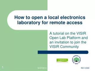
Summary part 1 - 3 • The VISIR laboratory is an enhancement of the local laboratory • The software representing almost 20 man-years of work is published and you are invited to join the VISIR group and contribute to the further development • The goal is producing engineers who have a solid and documented experience of laboratory work without increased cost per student for universities