Download
1 / 30
310 likes | 482 Vues
AERIALS AND RADIO FREQUENCY PROPAGATION. By Farhan Saeed. AERIALS. In any radio system information is superimposed on to a radio frequency carrier which is radiated into the atmosphere in the form of electromagnetic (e-m) energy.

E N D
AERIALS AND RADIO FREQUENCY PROPAGATION By Farhan Saeed
AERIALS • In any radio system information is superimposed on to a radio frequency carrier which is radiated into the atmosphere in the form of electromagnetic (e-m) energy. • An aerial or antenna, is a device for either radiating electromagnetic energy into space or collecting electromagnetic energy from space. • This electromagnetic energy is in the form of electric and magnetic fields, which are in turn related to the alternating currents (ac) which flow in the aerial.
Electro-Magnetic Wave • An EM wave consists of two fields, an oscillating Electric field (E) and an oscillating Magnetic field (H) which are always at right angles to one another. Electric Field Magnetic Field Magnetic Field Electric Field
Electro-Magnetic Wave • The two fields are always at right angles to one another. If the electric field is in the vertical position the EM wave is said to be vertically polarized. • The electro-magnetic radiation is generated at a transmitter by means of alternating current and is transmitted via an antenna. It travels in an all-round direction (omni-directional).
Frequency and wavelength + Time 0 - 1 Cycle Wavelength
Frequency and wavelength • Frequency is defined as the number of complete series of changes of, for example, an alternating current, which occur in 1 second, i.e. cycles per second. It is measured in Hertz (Hz), i.e. 1 cycle per second = 1 Hertz. • Wavelength is defined as the period of time it takes to complete one cycle and is expressed in metres. • The velocity of propagation of an electromagnetic (radio) wave through space is at the speed of light, i.e. 300 000 000 metres per second.
Frequency and wavelength • Frequency is defined as the number of cycles to pass a point in ONE SECOND OF TIME. It is measured in HERTZ (Hz) where 1 cycle per second = 1 Hertz. • The frequency of Electro-magnetic radiation is related to the wavelength by the equation: Frequency = Velocity (m/s) / Wavelength (m) F = V / λ
Frequency and wavelength • The velocity of an EM wave is variable, but for navigational aids purposes it is taken as being constant as a speed of 300 metres in 1 millionth of a second. (Known as a MICROSECOND). ( ) • It can be seen by the formula that if the frequency is increased, the wavelength will decrease or vice versa.
Frequency and wavelength • The lower the frequency, the greater the range, e. g., frequency of 100 kilohertz (100 thousand Hertz) is approximately 1200 miles, whereas, a frequency of 150 MHz (150 million Hertz) gives a range of 25 miles. • Calculation !
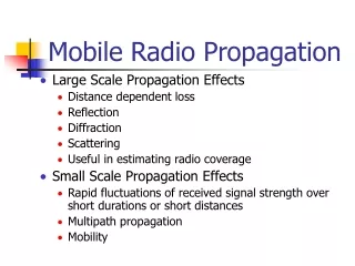
Propagation of Radio Wave • Propagation is concerned with the way that radio waves travel between a transmitter (Tx) and a receiver (Rx) at some distant point. • The radio frequency spectrum is divided into major bands, i.e. • VLF Very Low Frequency • LF Low Frequency • MF Medium Frequency • HF High Frequency • VHF Very High Frequency
Transmitter Aerial MF LF VLF
Very Low Frequency • 3 – 30 kHz • In this band the radio wave follows the curvature of the earth’s surface and is known as a ground or surface wave. • Given sufficient transmitter output power and high aerial arrays, world-wide communication is possible.
Very Low Frequency • Since there is not much bandwidth in this band of the radio spectrum, only the very simplest signals are used, such as for radionavigation. • VLF waves can penetrate water to a depth of roughly 10 to 40 m , depending on the frequency employed and the salinity of the water. • VLF is used to communicate with submarines near the surface. • VLF is also used for radio navigation beacons (alpha) and time signals (beta). • VLF is also used in electromagnetic geophysical surveys.
Low Frequency • 30 kHz – 300 kHz • In this band the radio wave again follows the curvature of the earth’s surface, i.e. ground or surface wave. • However, because the frequency is now higher, the radio wave is attenuated by the earth more quickly and so the range is reduced to approximately 1 to 2 thousand miles dependant upon transmitter output power. • Loran C transmissions at 100 kHz, give reliable accurate ground wave coverage up to 1200 miles.
Low Frequency • Used for • AM Broadcast service • LORAN • Weather system • Time signals
Medium Frequency • 300 kHz – 3000 kHz • Uses ground or surface wave, but because the frequency is now even higher, the range is reduced. • The actual range of communication now depends upon both the transmitter output power and on the type of information being transmitted. • MF RT 2182 kHz 150 to 200 miles, • MF DSC 2187.5 kHz approximately 400 miles • Navtex 518 kHz • The range on MF RT is less because the bandwidth is higher and therefore susceptible to attenuation.
High Frequency • High Frequency • 3 MHz – 30 MHz • The HF band is so big that we tend to sub-divide it into those which are used for maritime communications, i.e. 4, 6, 8, 12, 16 and 22 MHz.
Very High Frequency • 30 MHz – 300 MHz • On VHF, UHF and SHF bands, the radio waves travel in straight lines and are known as direct or space waves, i.e. line of sight communication. • The main consideration which determines the range obtainable is the height of both the receiving and transmitting aerials are above sea level, i.e. an increase in height gives an increase in range.
Frequency and wavelength • Any Questions ?
Hyperbolic Line • A hyperbolic line may be defined as a line joining all points where the DIFFERENCE IN DISTANCE from two places IS THE SAME. • The distance mentioned can be a measurement of any unit, e.g., metres or miles OR, in the case of navigational systems, radio waves where the difference can be measured either by phase difference or time difference.
Hyperbolic Line • Long base lines have the advantage over short baselines because the hyperbolic lines are nearly parallel and therefore do not diversify as greatly. • A ship at position P and position Q ? • Ambiguity !
Time Difference • Hyperbolic systems depend upon the fact that if signals are transmitted from separate shore stations, the difference in the times of their arrival at a ship is a measure of the difference in distance of the ship from the two stations. • The signals may be sent in pulses so that the time between receiving the pulses may be measured. • Loran C uses this system, and once again the system is operated in such a way that the Master station pulse is always received first.
Time Difference • Given a time difference and knowing the velocity of radio waves, the distance difference can be found. • In a system measuring time difference (Loran C), the hyperbolic lines are drawn on the chart representing the time difference in micro-seconds between receiving the two transmissions.
Time Difference • Given a time difference and knowing the velocity of radio waves, the distance difference can be found. • In a system measuring time difference (Loran C), the hyperbolic lines are drawn on the chart representing the time difference in micro-seconds between receiving the two transmissions.
Lattice chart • A lattice chart is a chart which has a family of hyperbolic lines drawn on it. Since the lines cross and cut one another, it gives the appearance of ‘lattice’ work, hence the word, ‘lattice’ • In the Loran C system, the lattice lines are drawn on a Loran chart. When the ship’s position is fixed on one of these charts, the position may be transferred to the Admiralty chart.
Hyperbolic System • Any Questions !