Download
1 / 63
630 likes | 839 Vues
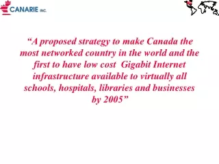
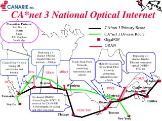
CA*net 3 National Optical Internet. Consortium Partners: Bell Nexxia Nortel Cisco JDS Uniphase Newbridge. CA*net 3 Primary Route. CA*net 3 Diverse Route . GigaPOP. ORAN. Deploying a 4 channel CWDM Gigabit Ethernet network – 700 km.

E N D
CA*net 3 National Optical Internet Consortium Partners: Bell Nexxia Nortel Cisco JDS Uniphase Newbridge CA*net 3 Primary Route CA*net 3 Diverse Route GigaPOP ORAN Deploying a 4 channel CWDM Gigabit Ethernet network – 700 km Deploying a 4 channel Gigabit Ethernet transparent optical DWDM– 1500 km Condo Dark Fiber Networks connecting universities and schools Condo Fiber Network linking all universities and hospital Multiple Customer Owned Dark Fiber Networks connecting universities and schools Netera MRnet SRnet ACORN St. John’s BCnet Calgary Regina Winnipeg Charlottetown RISQ ONet Fredericton Montreal Vancouver 16 channel DWDM -8 wavelengths @OC-192 reserved for CANARIE -8 wavelengths for carrier and other customers Halifax Ottawa Seattle STAR TAP Toronto Chicago New York
MREN Moscow CA*net 3 International DANTE New York Europe Seattle Germany CA*net 3 Sweden Holland Asia APAN Japan Taiwan Singapore ESnet NTT OC3 Moscow STAR TAP MIRnet vBNS Internet 2 Abilene Internet-2 NASA
CA*net 3 Objectives • In partnership with carrier, industry and regional networks carry out research, development and testing in Optical Internet technologies and strategies • Showcase Canadian industry optical Internet technologies and services • Technology development leading to the creation of sustainable high performance networking environment for the research and education community • Technology development towards a high performance “Canadian content” delivery network for Schoolnet, CAP, etc • Development of the 3rd generation Internet based on optical networking technologies
What is an Optical Internet? • WDM fibers where individual wavelengths are the link layer interconnect directly connected to routers via Optical ADM (Add Drop Mux) or WDM coupler • High Performance Router acts as the main switching routing device • Bypass or cut-thru connections via dedicated wavelengths • SONET or Gigabit Ethernet framing (also 10xGbE or SDL) • Use intrinsic self healing nature of Internet for redundancy and protection (don’t require SONET/SDH layer) • Traffic engineering and network management done via MPLS • Network design optimized for unique characteristics of Internet traffic – fractal traffic, asymmetric traffic and congestion at the edge
Types of Optical Internets • SONET switched – OEO • MPLS for control of OC-x channels • IGP optical networks -variants of PNNI, OSPF e.g. WARP, etc • POS and EOS • Layer 1 restoral & protection using SONET • All optical transparent • Static wavelength provisioning • IGP & MPLS on essentially dumb links; or • iBGP and EGP • POS and EOS or native GbE and 10GbE and others • Layer 1 optical restoral and Layer 3 restoral (MPLS or IGP) • Enterprise autonomous optical networks • OBGP and wavelength arbiter for autonomous peering and joins • BGP peering sessions determine optical links • All optical burst switching and routing • MPLS label used as burst optical switch • Packet switching or flow switching?
Types of Long Haul GbE • SONET framed – EOS • Ideal for legacy carrier SDH/SONET and DWDM systems • Bridged architecture • Complex flow control to map Ethernet 10/100/1000 to OC-x • Layer 1 restoral & protection using SONET • SONET framing for DWDM wavelength modulation skirt and OAM&P • OEO transport with regenerators and digital wrapper • Digital Wrapper required for management of link and modulation skirt • Carry native GbE and 10GbE and others within wrapper • Layer 1 optical restoral • All optical transport – CWDM and DWDM • Broadband optical in S,L,C bands • Native xGbE with CWDM and wide modulation skirts • Low efficiency – 36% overhead • Enterprise autonomous optical networks • Native GbE for framing on link • Flow control at TCP – low efficiency
Characteristics of Internet Traffic • Internet traffic does not aggregate – it remains fractal or bursty at all traffic volumes • Internet traffic is very asymmetric with ratios of up to 16:1 between transmit and receive paths • Internet traffic is predominantly made up of computer to computer traffic (and growing despite all the talk about multimedia, interactive video and VoIP) • E.g caching updates, e-mail, network news, huge file xfer, application servers • Computer to computer traffic can easily tolerate packet loss, latency and jitter • Server performance, DNS, routing tables, etc have bigger impact on Internet reliability than the underlying physical network • Physical network reliability contributes to less than 40% of overall Internet outages and delays • Mathematically shown that multiple connections to Internet more reliable than one connection with 99.999 reliability
Fractal Internet OC3c OC3c 1 user Average Load Average Load 100 users Need big buffers or big bandwidth Average Load Average Load 1 million users Traditional Voice Traffic Internet Traffic
Implications of Fractal Bandwidth • With fractal bandwidth reserved bandwidth channels causes more congestion than one shared channel of equivalent bandwidth • In the Internet it is more important to prioritize traffic by packet loss and latency rather than by reserved bandwidth • Layer 3 restoral mechanism make more sense than layer 1 restoral and protection with highly fractal traffic • If 50 msec average traffic load is less than 50% • Therefore easier to double up traffic on an existing link and introduce slightly longer microsecond delays to non-priority traffic • Therefore both protection and working path can be optimized for fractal traffic
Bandwidth Models A Ideal for multicast streaming e.g. DSL 1 Mbps 1 Mbps B 1 Mbps C OR Ideal for fractal or bursty traffic such as web traffic 3 Mbps B C A With simple QoS green can be delayed microseconds to give even better efficiency
Why 10/100 Mbps in the LAN? • If you add up the average bandwidth consumption in a typical LAN it will not come anywhere close to even 2 Mbps • So why not build a cheaper 2 Mbps LAN instead? • The driver for big bandwidth is congestion avoidance • Everybody hates waiting seconds for their e-mail while the network is tied up with a big print job or file transfer • This same force is at play in the WAN except costs are a limiting factor • Most enterprise customers operate large LAN networks with miles of copper and fiber and many switches • adding a 10-50 km single link extension is a no brainer • But dark fiber and GbE dramatically changes costs and LAN economics and engineering can move to the WAN
20:1 Cnet Regional Network 4:1 To Other Regionals 6:1 Backbone Network 3:1 2:1 Big Server e.g. Netscape Big Server e.g. Microsoft Tx:Rx Tx/Rx Asymmetry
Three types of traffic • Human to Human • real time voice and video, tele-medicine, tele-immersive VR, etc • very sensitive to jitter and delay • very symmetric & growing linearly • usually one to one connections so QoS easy • Human to Computer • web, voice mail, video servers, call centers, fax - mostly TCP • jitter and delay can be compensated with client buffering • fractal & very asymmetric & growing exponentially • usually many to one connections so QoS very hard • Computer to Computer (usually many to many) • E-mail, FTP, IP appliances, application servers, content caching • insensitive to jitter and delay, but extremely fractal • extremely asymmetric & growing exponentially plus • Usually many to many connections so QoS extremely hard
Computer will drive network architectures • Computer central processor does not shut down 8 hours a night • Computers can talk all day and all night, 365 days a year. • You don’t need 2 computers to create another computer • Millions of computers will be located everywhere • Computers are very tolerant of network congestion, packet loss, outages, etc • Computers can consume all the offered bandwidth – the only limitation is the cost of bandwidth • So today we artificially restrict available bandwidth • Designing networks for computers is a lot easier and cheaper than a network for humans e.g. Internet, CA*net 3
We already have Petabit Networks • FedX is already a Petabit network • thousands of disks and tapes shipped daily • jitter and latency is pretty poor • cost for shipping tape approx .000001 cents/byte • Current cost of sending data over fiber .001cents/byte • With an optical Internet data will cost .00001 cents/byte • By 2001 telecommunication cost will be close to FedX cost • If 10% of this traffic moves to the Internet, the Internet will be bigger than all voice networks combined • This is all computer to computer traffic – ideal for the Internet • Most university traffic still moves by tape
Caching key component of 99.999 Internet • Speed of fastest packet transfer across the country (>50 msec) is 10x slower than disk speed access • Today’s bandwidth prices • At the center -- $800/Mbit/sec/mo • “on network” -- $400/Mbit/sec/mo • “at the edge” -- $0 (co location fees ~$1K/mo) • A disk drive as a source of bandwidth • $500, 5Mbits/sec (cache) = $3/Mbit/sec/mo! • RAM as a source of bandwidth • $2000 (1GByte), 100MBits/sec = $1/Mbit/sec/mo • So better investment is spend money on intelligent storage rather than the network • Traffic between intelligent storage is computer to computer
DNS critical to 99.999 Internet • You ask for www.yahoo.com/graphic1.gif • Want that request sent to optimized server • Where you are in the network • How loaded the servers are • Where bad things are happening in the network • Possible mechanisms • HTTP redirect • IP redirect • DistributedDirector style DNS • Optimized DNS solutions • For large distributed content caches DNS solutions are only practical solutions
Early Indicators • Biggest bandwidth consumers on IP networks are NNTP, HHTP caching, intelligent storage and FTP • Internet 2 has carried out one FTP session that took over a month! • On CA*net 3 biggest applications is NRC Bioinformatics – 40 servers across the country constantly updating each other • Researchers say biggest need is bandwidth to transfer large data files • In the commercial world application servers and content caching are increasingly the biggest applications • Even video may be a computer to computer connection because of caching • If customer has enough disk easier to send movie as an FTP file then by streaming • No no biological limitations to number of computers and can talk all day and night
DNS 13% Server Connect 33% 12% Bellcore Study C Huitema 23/1/97 Network 42% Web Points of Congestion
Building a 99.999 Internet • Most Internet congestion and packet loss is caused by the destination server and NOT the network • Usually the weakest link is DNS on most Internet networks • Even on links with BER of 10^-15 there is 1-3% packet loss due to TCP packet loss and retransmission • Packet loss and retransmission is an essential feature of the Internet for server to server flow control • Many ISPs deliberately create packet loss for flow control- RED • so BER due to TCP is 10^-6 to 10^-8. BER of 10^-15 is irrelevant - a poor BER is not necessarily a bad thing • Paul Baran in the mid 60’s demonstrated mathematically you can get a more reliable network with multiple paths than with a single path and 99.999 reliable equipment • A network with multiple paths, full DNS and http caching can be more reliable than a binary SONET network
50 msec restoral myth • Traditional telco networks absolutely require fast restoral because they are connection oriented networks • If an outage is not restored quickly all telephone circuits, frame relay circuits and ATM circuits are dropped • The load on the SS7 network is horrific when all these circuits then try to signal to re-establish a connection at the same time • But connectionless oriented networks simply re-route packets via an alternate route • So connectionless oriented circuits only need fast restoral to prevent a break in voice or video transmission for a couple of seconds • But how important is this to the user? • How many times a year will a user experience a 2 or 10 second disruption in their video or audio due to a fiber break?
QoS Myth • QoS is needed in one to one connections for real time voice and video e.g • Doctor video conferencing with a patient • BUT, most Internet applications are NOT one to one real time connections, they are many to one and many to many type of connections e.g. • Doctors retrieving X-ray image from a database • Multicast distribution of a movie etc • Many users going to the same web site • End to end QoS is real hard if you have more than a one to one, real time connection • The only practical solution is “good enough” QoS at congestion points e.g. diff serv
CA*net 3 Design Implications • Future traffic could be high volume, high fractal TCP “computer to computer” with lots of empty space for other types of traffic • Large peak to average loads to accommodate fractal nature of Internet • Smaller volume, jitter sensitive “human to human” traffic can be inserted in empty space prioritized with simple QoS mechanisms • Network reliability and performance must be defined from a systems level, not a network level • Throughput and congestion are increasingly server bound, not network bound • So high bandwidth IP pipes using protection fiber to provide multiple paths with simple QoS and reliability mechanisms may be all that is needed
Traditional Internet Architecture Router Router VCs VCs ATM switch ATM switch OC3 OC3 OC12 OC12 SONET Mux SONET Mux OC3 OC3 Working Fiber OC48 OC48 SONET Transport SONET Transport SONET/SDH Ring Protection Fiber
Optical Internet Architecture“Rings are Dead” Both sides of fiber ring ring used for IP traffic Traditional SONET Transport Node Traditional SONET Transport Node WDM WDM 3 0C-48 Tx 2 OC-48 Rx High Priority Traffic Cannot exceed 50% of bandwidth in case of fiber cut Asymmetric Tx/Rx lambdas that can be dynamically altered Traditional SONET Restoral Low priority traffic that can be buffered or have packet loss in case of fiber cut
DCS TransportNode Traditional SONET Network Node Carrier Tributary SONET services - OC3c, OC12c, etc WDM Coupler WDM Coupler OC-48/192 Working Fiber Working Fiber To Local GigaPOP (ATM, SONET, WDM etc) To Local GigaPOP (ATM, SONET, WDM, (etc) Carrier Router Transponders WDM Coupler WDM Coupler Electrical Regenerator OC-48/192 Cut thru asymmetric Lambdas to next Router Protection Fiber Protection Fiber
Layer 3 Restoral • IP network is intrinsically self healing via routing protocols • By cranking down timers on interface cards and keep alive message time-out we can achieve 1/3 second restoral • Biggest delay is re-calculation and announcement of changes in routing tables across the network • MPLS promises to simply the problem • maintain a set of attributes for restoral and optimization • may provide a consistent management interface over all transport services -WDM, SONET/SDH, ATM, Frame Relay, etc • 50 msec restoral possible with MPLS • Layer 3 restoral allows for more intelligent restoral • can use a hybrid mix of restoral and protection circuits • Can use QoS to prioritize customers and services • Only UDP packets (e.g telephony) require fast restoral • allows simultaneous use of both working and protection circuits
Lessons Learned - 1 • Carrier transport people now must learn to deal with customers directly • Require network management tools that give customer a view of “their” wavelengths • A whole new set of operating procedures required • L3 must understand L1, L2 to troubleshoot problems • L1, L2 must understand L3 or take direction from L3 NOC • No demarcation point in the network for L1 • Router terminates section/line/path • L3 may be responsible for proving circuit as L1, L2 may not have the tools • Need more L1/L2 diagnostics in L3 line card • OAM&P issues between router vendors and DWDM remain a challenge • SONET management systems expect to see a contiguous network • CA*net 3 required DCC work arounds • Need network tools to measure end to end performance and throughput at OC-48 or greater speeds – • HP is about to release a couple of beta products
Lessons Learned -2 • MPLS is proving a lot more difficult in practice to implement • Need tools for management of tunnels • Need Inter-domain MPLS-TE • Mythology of 50msec “fast restoral” still not understood • OSPF with very short hold down timers and GRE tunnels or policy routing may be an adequate alternative • Need MPLS management tools for explicit tunnels etc • Speed of light is a major problem • End computers must implement RFC 1323 to take advantage of high bandwidth • Speed of light latency across Canada (>50 msec) is 10x slower than disk access speed • Still very few sustainable “research” applications • Major problem is that bottle necks remain in the last mile and the last inch • Local loops and campus networks need significant upgrading to get end to end performance
If we could do it all over again… • Build our own national dark fiber with CWDM/DWDM in partnership with a carrier who wants to offer dark fiber or optical Internet services to business and home • Or get 20 year IRUs on dim wavelengths • Don’t build test networks – build production networks • We did survey and found very little interest in “crash and burn” test networks • Don’t build research networks – build Internet networks • If network carries commodity traffic – build it and they will run to you • The three new killer apps have come from universities and schools on the commodity networks • Napster, imesh, machinima • If network is for research traffic – build it and they will trickle in • Spend more time on demos than on applications • With optical Internets there will be enough bandwidth for both research and commodity traffic • Try to establish as many SKA peering interconnections with smaller ISPs as possible • Layer 3 switches rather than routers except at major peering points • Use new 10GbE for long haul
The driver for Optical Internet • Traditional OC-48 SDH/SONET network costs about $US 4000 - $5000 km per year • before overhead, engineering and maintenance • Optical Internet with today’s technology costs about $US 500-$750 per kilometer per year • With low cost regen (e.g.10xGbE), low dispersion fiber, and long range optical amplifiers optical Internet will cost $US 100 - $200 per km per year • Even more dramatic savings with metro local loops • Optical Internet also has significantly less overhead, engineering and maintenance costs. • see Engineering paper http://www.canet2.net for financial analysis
10Gigabit Ethernet &CWDM • Several companies have announced long haul GbE and CWDM with transceivers at 50km spacing • 10GbE coming shortly • IEEE 802.3 developing standards for 10GbE in the WAN • Native 10GbE, mapped to wavelength and EOS • Future versions will allow rate adaptive clocking for use with “gopher bait” fiber, auto discovery, CPE self manage • Excellent jitter specification • Most network management and signaling done at IP layer • Anybody with LAN experience can build a long haul WAN – all you need is dark fiber • With CWDM, no EDFA power disbursement and gain tilt • Repeater distance independent number of wavelengths
Importance of xGbE for CWDMBricks and mortar more expensive than fiber Different Dispersion and Attenuation at different wavelengths. So to maintain same repeater spacing must have different clock rates. CWDM spacing allows wider modulation skirts so data rates above 10GbE are also possible. Also data rate can vary to compensate for variations in PMD Dispersion 14GbE 4GbE 16GbE 6GbE 10GbE 8GbE 12GbE 1550 1310
Compare to DWDM Wavelengths are tightly packed together so therefore spectral width must be tightly maintained i.e.one clock frequency and one modulation schema Dispersion 1550 1310
Costs for IP/DWDM SONET Transport Terminal WDM Coupler $20K 50 km Transponder Wideband Optical Repeater $250K SONET Regen $250k per Tx/Rx 250 km Terabit Router $400K For transponder currently using regen box $125K Approximate Distances for OC-192 system Typical Cost $6000 per km (not counting cost of fiber router, and transponder) for one OC-192 channel Advantage – can support multi-services and well known technology Disadvantage – Repeater spacing dependent on number of wavelengths and power
G G G G Costs for 10GbE CWDM 50 km CWDM Coupler $5K 10xGbE Switch $20K 10x Transceiver $20K Approximate Distances for 10xGbE system Typical Cost $400 per km (not counting cost of fiber or 10xGbE switches) for 10 Gbps Advantage – very low cost 1/10 cost of SONET & DWDM - repeater spacing independent of number of wavelengths and power budget Disadvantage – requires 2 fibers and can only carry IP (or GbE) traffic
O-BGP (Optical BGP) • Control of optical routing and switches across an optical cloud is by the customer – not the carrier • A radical new approach to the challenge of scaling of large networks • Use establishment of BGP neighbors or peers at network configuration stage for process to establish light path cross connects • Edge routers have large number of direct adjacencies to other routers • Customers control of portions of OXC which becomes part of their AS • Optical cross connects look like BGP speaking peers • BGP peering sessions are setup with separate TCP channel outside of optical path or with a Lightpath Route Arbiter • All customer requires from carrier is dark fiber, dim wavelengths, dark spaces and dumb switches • Traditional BGP gives no indication of route congestion or QoS, but with DWDM wave lengths edge router will have a simple QoS path of guaranteed bandwidth • Wavelengths will become new instrument for settlement and exchange eventually leading to futures market in wavelengths • May allow smaller ISPs and R&E networks to route around large ISPs that dominate the Internet by massive direct peerings with like minded networks
Current View of Optical Internets ISP AS 1 AS 4 Customers buy managed service at the edge Optical VLAN AS 1 Customer AS 3 BGP Peering is done at the edge Big Carrier Optical Cloud using MPLS and IGP for management of wavelengths for provisioning, restoral and protection AS 2
OBGP Optical Internets Customer is now responsible for wavelength configuration, restoral and protection ISP Customer BGP Peering is done inside the optical switch BGP Big Carrier Optical Cloud disappears other than provisioning of electrical power to switches
BGP Routing L0 172.16.2.254 255.255.255.255 BGP Neighbor BGP Neighbor 2.2.2.1 L0 172.16.90.1 255.255.255.255 L0 172.16.40.1 255.255.255.255 Router B 1.1.1.1 1.1.1.2 180.10.10.0 2.2.2.2 Router A Router C AS 200 170.10.10.0 190.10.10.0 AS 100 AS 300 Figure 1.0
BGP Routing + OXC = OBGP AS 200 180.10.10.0 BGP Neighbor BGP Neighbor 1.1.1.1 3.3.3.1 Router B Metric 100 Metric 100 3.3.3.2 4.4.4.1 1.1.1.2 2.2.2.1 Router A Metric 200 Metric 200 Router C 2.2.2.2 4.4.4.2 AS 300 190.10.10.0 AS 100 170.10.10.0 Figure 2.0
Virtual BGP Router L0 172.16.2.254 255.255.255.255 BGP Neighbor BGP Neighbor 2.2.2.1 L0 172.16.90.1 255.255.255.255 L0 172.16.40.1 255.255.255.255 Router B 1.1.1.1 1.1.1.2 2.2.2.2 180.10.10.0 Router A 4.4.4.1 Router C 3.3.3.2 4.4.4.2 3.3.3.1 170.10.10.0 190.10.10.0 L0 172.16.1.254 255.255.255.255 AS 100 AS 300 AS 200 BGP Neighbor BGP Neighbor Figure 4.0
Fiber ring OIX with OBGP AS 200 170.10.10.0 Institution A BGP Peering Relationships Institution C Institution B AS 300 180.10.10.0 AS 100 160.10.10.0 Institution D AS 400 190.10.10.0 Figure 9.0
OIX using OBGP AS 200 170.10.10.0 Institution A Lightpath Route Arbiter Switch Ports are part of institution’s AS Institution B AS 300 180.10.10.0 AS 100 160.10.10.0 Institution C Institution D AS 400 190.10.10.0 Figure 10.0
OBGP Networks Dark fiber Network City X Dark fiber Network City Y ISP B ISP A EGP ISP C AS100 EGP AS200 To other Wavelength Clouds Wavelength Routing Arbiter & ARP Server AS300 AS400 Customer Owned Dim Wavelength EGP Dark fiber Network City Z ISP B ISP A Figure 11.0
CA*net 4 – Distributed OIX AS 549 ONet AS 271 BCnet AS 376 RISQ OBGP OBGP OBGP New York Seattle Chicago Figure 12.0
Overall Objective • To deploy a novel new optical network that gives GigaPOPs at the edge of the network (and ultimately their participating institutions) to setup and manage their own wavelengths across the network and thus allow direct peering between GigaPOPs on dedicated wavelengths and optical cross connects that they control and manage • To allow the establishment of wavelengths by the GigaPOPs and their participating institutions in support of QoS and grid applications • To allow connected regional and community networks to setup transit wavelength peering relationships with similar like minded networks to reduce the cost of Internet transit • To offer an “optional” layer 3 aggregation service for those networks that require or want such a facility
CA*net 4 Physical Architecture Optional Layer 3 aggregation service Dedicated Wavelength or SONET channel St. John’s Regina Winnipeg Charlottetown Calgary Europe Vancouver Montreal Large channel WDM system Fredericton Halifax OBGP switches Seattle Ottawa Chicago New York Los Angeles Toronto Miami
OBGP Objectives • OBGP Traffic Engineering • To build a mesh of optical switches such that the network operator can carry out traffic engineering by moving high traffic BGP peers to an optical cross connect • OBGP QoS • To build an optical network that will support the establishment of direct optical channels by the end used between BGP speakers to guarantee QoS for peer to peer networking and or grid applications between attached regional research or community networks • OBGP Optical Peering • To provide a peering transit service such that any BGP speaking regional research or community network can establish a direct peer with any other BGP speaking peer through the establishment of an direct optical channel in response to the request to establish the peer. • OBGP Large Scale • To prototype the technology and management issues of scaling large Internet networks where the network cloud is broken into BGP regions and treated as independent customers
OBGP Traffic Engineering - Physical Tier 1 ISP Tier 2 ISP Intermediate ISP Router redirects networks with heavy traffic load to optical switch, but routing policy still maintained by ISP Optical switch looks like BGP router and AS1 is direct connected to Tier 1 ISP but still transits AS 5 AS 5 Red Default Wavelength AS 4 AS 3 AS 2 AS 1 Bulk of AS 1 traffic is to Tier 1 ISP For simplicity only data forwarding paths in one direction shown Dual Connected Router to AS 5