
Shear and Moment Diagrams for Bending Stress Analysis
E N D
Presentation Transcript
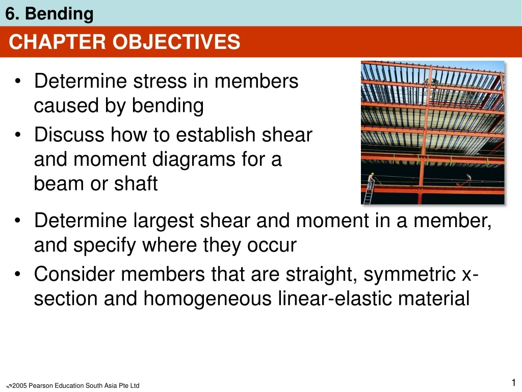
CHAPTER OBJECTIVES • Determine stress in members caused by bending • Discuss how to establish shear and moment diagrams for a beam or shaft • Determine largest shear and moment in a member, and specify where they occur • Consider members that are straight, symmetric x-section and homogeneous linear-elastic material
CHAPTER OBJECTIVES • Consider special cases of unsymmetrical bending and members made of composite materials • Consider curved members, stress concentrations, inelastic bending, and residual stresses
CHAPTER OUTLINE • Shear and Moment Diagrams • Graphical Method for Constructing Shear and Moment Diagrams • Bending Deformation of a Straight Member • The Flexure Formula • Unsymmetrical Bending • *Composite Beams • *Reinforced Concrete Beams • *Curved Beams • Stress Concentrations • *Inelastic Bending • *Residual Stress
6.1 SHEAR AND MOMENT DIAGRAMS • Members that are slender and support loadings applied perpendicular to their longitudinal axis are called beams
6.1 SHEAR AND MOMENT DIAGRAMS • In order to design a beam, it is necessary to determine the maximum shear and moment in the beam • Express V and M as functions of arbitrary position x along axis. • These functions can be represented by graphs called shear and moment diagrams • Engineers need to know the variation of shear and moment along the beam to know where to reinforce it
6.1 SHEAR AND MOMENT DIAGRAMS • Shear and bending-moment functions must be determined for each region of the beam between any two discontinuities of loading
6.1 SHEAR AND MOMENT DIAGRAMS Beam sign convention • Although choice of sign convention is arbitrary, in this course, we adopt the one often used by engineers:
6.1 SHEAR AND MOMENT DIAGRAMS IMPORTANT • Beams are long straight members that carry loads perpendicular to their longitudinal axis. They are classified according to how they are supported • To design a beam, we need to know the variation of the shear and moment along its axis in order to find the points where they are maximum • Establishing a sign convention for positive shear and moment will allow us to draw the shear and moment diagrams
6.1 SHEAR AND MOMENT DIAGRAMS Procedure for analysis Support reactions • Determine all reactive forces and couple moments acting on beam • Resolve all forces into components acting perpendicular and parallel to beam’s axis Shear and moment functions • Specify separate coordinates x having an origin at beam’s left end, and extending to regions of beam between concentrated forces and/or couple moments, or where there is no discontinuity of distributed loading
6.1 SHEAR AND MOMENT DIAGRAMS Procedure for analysis Shear and moment functions • Section beam perpendicular to its axis at each distance x • Draw free-body diagram of one segment • Make sure V and M are shown acting in positive sense, according to sign convention • Sum forces perpendicular to beam’s axis to get shear • Sum moments about the sectioned end of segment to get moment
6.1 SHEAR AND MOMENT DIAGRAMS Procedure for analysis Shear and moment diagrams • Plot shear diagram (V vs. x) and moment diagram (M vs. x) • If numerical values are positive, values are plotted above axis, otherwise, negative values are plotted below axis • It is convenient to show the shear and moment diagrams directly below the free-body diagram
EXAMPLE 6.6 Draw the shear and moment diagrams for beam shown below.
EXAMPLE 6.6 (SOLN) Support reactions: Shown in free-body diagram. Shear and moment functions Since there is a discontinuity of distributed load and a concentrated load at beam’s center, two regions of x must be considered. 0 ≤x1 ≤5 m, +↑ Fy = 0; ... V = 5.75 N + M = 0; ... M = (5.75x1 + 80) kN·m
EXAMPLE 6.6 (SOLN) Shear and moment functions 5 m ≤x2 ≤10 m, +↑ Fy = 0; ... V = (15.75 5x2) kN + M = 0; ... M = (5.75x22 + 15.75x2 +92.5) kN·m Check results by applyingw = dV/dx and V = dM/dx.
EXAMPLE 6.6 (SOLN) Shear and moment diagrams
6.2 GRAPHICAL METHOD FOR CONSTRUCTING SHEAR AND MOMENT DIAGRAMS • A simpler method to construct shear and moment diagram, one that is based on two differential equations that exist among distributed load, shear and moment
6.2 GRAPHICAL METHOD FOR CONSTRUCTING SHEAR AND MOMENT DIAGRAMS Regions of distributed load dM dx dV dx = V = w(x) Slope of shear diagram at each point = distributed load intensity at each point Slope of moment diagram at each point = shear at each point
6.2 GRAPHICAL METHOD FOR CONSTRUCTING SHEAR AND MOMENT DIAGRAMS Regions of distributed load V =∫ w(x) dx M =∫ V(x) dx Change in shear = area under distributed loading Change in moment = area under shear diagram
6.2 GRAPHICAL METHOD FOR CONSTRUCTING SHEAR AND MOMENT DIAGRAMS Regions of concentrated force and moment
6.2 GRAPHICAL METHOD FOR CONSTRUCTING SHEAR AND MOMENT DIAGRAMS Regions of concentrated force and moment
6.2 GRAPHICAL METHOD FOR CONSTRUCTING SHEAR AND MOMENT DIAGRAMS Procedure for analysis Support reactions • Determine support reactions and resolve forces acting on the beam into components that are perpendicular and parallel to beam’s axis Shear diagram • Establish V and x axes • Plot known values of shear at two ends of the beam
6.2 GRAPHICAL METHOD FOR CONSTRUCTING SHEAR AND MOMENT DIAGRAMS Procedure for analysis Shear diagram • Since dV/dx = w, slope of the shear diagram at any point is equal to the (-ve) intensity of the distributed loading at that point • To find numerical value of shear at a point, use method of sections and equation of equilibrium or by using V =∫ w(x) dx, i.e., change in the shear between any two points is equal to (-ve) area under the load diagram between the two points
6.2 GRAPHICAL METHOD FOR CONSTRUCTING SHEAR AND MOMENT DIAGRAMS Procedure for analysis Shear diagram • Since w(x) must be integrated to obtain V, then if w(x) is a curve of degree n, V(x) will be a curve of degree n+1 Moment diagram • Establish M and x axes and plot known values of the moment at the ends of the beam • Since dM/dx = V, slope of the moment diagram at any point is equal to the shear at the point
6.2 GRAPHICAL METHOD FOR CONSTRUCTING SHEAR AND MOMENT DIAGRAMS Procedure for analysis Moment diagram • At point where shear is zero, dM/dx = 0 and therefore this will be a point of maximum or minimum moment • If numerical value of moment is to be determined at the point, use method of sections and equation of equilibrium, or by using M =∫ V(x) dx, i.e., change in moment between any two pts is equal to area under shear diagram between the two pts
6.2 GRAPHICAL METHOD FOR CONSTRUCTING SHEAR AND MOMENT DIAGRAMS Procedure for analysis Moment diagram • Since V(x) must be integrated to obtain M, then if V(x) is a curve of degree n, M(x) will be a curve of degree n+1
EXAMPLE 6.11 Draw the shear and moment diagrams for beam shown below.
EXAMPLE 6.11 (SOLN) Support reactions: See free-body diagram. Shear diagram From behavior of distributed load, slope of shear diagram varies from zero at x = 0 to 2 at x = 4.5. Thus, its parabolic shape. Use method of sections to find point of zero shear: +↑ Fy = 0; ... x = 2.6 m
EXAMPLE 6.11 (SOLN) Moment diagram From shear diagram, slope of moment diagram begin at +1.5, then decreases positively till it reaches zero at 2.6 m. Then it increases negatively and reaches 3 at x = 4.5 m. Moment diagram is a cubic function of x. + M = 0; . . . M = 2.6 kN·m
6.3 BENDING DEFORMATION OF A STRAIGHT MEMBER • When a bending moment is applied to a straight prismatic beam, the longitudinal lines become curved and vertical transverse lines remain straight and yet undergo a rotation
6.3 BENDING DEFORMATION OF A STRAIGHT MEMBER • A neutral surface is where longitudinal fibers of the material will not undergo a change in length.
6.3 BENDING DEFORMATION OF A STRAIGHT MEMBER • Thus, we make the following assumptions: • Longitudinal axis x (within neutral surface) does not experience any change in length • All cross sections of the beam remain plane and perpendicular to longitudinal axis during the deformation • Any deformation of the cross-section within its own plane will be neglected • In particular, the z axis, in plane of x-section and about which the x-section rotates, is called the neutral axis
= (y/c)max 6.3 BENDING DEFORMATION OF A STRAIGHT MEMBER • For any specific x-section, the longitudinal normal strain will vary linearly with y from the neutral axis • A contraction will occur () in fibers located above the neural axis (+y) • An elongation will occur (+) in fibers located below the axis (y) Equation 6-8
= (y/c)max 6.4 THE FLEXURE FORMULA • Assume that material behaves in a linear-elastic manner so that Hooke’s law applies. • A linear variation of normal strainmust then be the consequence ofa linear variation in normal stress • Applying Hooke’s law to Eqn 6-8, Equation 6-9
∫A y dA= 0 max c M = ∫A y2 dA 6.4 THE FLEXURE FORMULA • By mathematical expression, equilibrium equations of moment and forces, we get Equation 6-10 Equation 6-11 • The integral represents the moment of inertia of x-sectional area, computed about the neutral axis. We symbolize its value as I.
Mc I max = 6.4 THE FLEXURE FORMULA • Hence, Eqn 6-11 can be solved and written as Equation 6-12 max = maximum normal stress in member, at a pt on x-sectional area farthest away from neutral axis M = resultant internal moment, computed about neutral axis of x-section I = moment of inertia of x-sectional area computed about neutral axis c = perpendicular distance from neutral axis to a pt farthest away from neutral axis, where max acts
My I = 6.4 THE FLEXURE FORMULA • Normal stress at intermediate distance y can be determined from Equation 6-13 • is -ve as it acts in the -ve direction (compression) • Equations 6-12 and 6-13 are often referred to as the flexure formula.
6.4 THE FLEXURE FORMULA • IMPORTANT • X-section of straight beam remains plane when beam deforms due to bending. • The neutral axis is subjected to zero stress • Due to deformation, longitudinal strain varies linearly from zero at neutral axis to maximum at outer fibers of beam • Provided material is homogeneous and Hooke’s law applies, stress also varies linearly over the x-section
6.4 THE FLEXURE FORMULA • IMPORTANT • For linear-elastic material, neutral axis passes through centroid of x-sectional area. This is based on the fact that resultant normal force acting on x-section must be zero • Flexure formula is based on requirement that resultant moment on the x-section is equal to moment produced by linear normal stress distribution about neutral axis
6.4 THE FLEXURE FORMULA • Procedure for analysis • Internal moment • Section member at pt where bending or normal stress is to be determined and obtain internal moment M at the section • Centroidal or neutral axis for x-section must be known since M is computed about this axis • If absolute maximum bending stress is to be determined, then draw moment diagram in order to determine the maximum moment in the diagram
6.4 THE FLEXURE FORMULA • Procedure for analysis • Section property • Determine moment of inertia I, of x-sectional area about the neutral axis • Methods used are discussed in Textbook Appendix A • Refer to the course book’s inside front cover for the values of I for several common shapes
6.4 THE FLEXURE FORMULA • Procedure for analysis • Normal stress • Specify distance y, measured perpendicular to neutral axis to pt where normal stress is to be determined • Apply equation = My/I, or if maximum bending stress is needed, use max = Mc/I • Ensure units are consistent when substituting values into the equations
EXAMPLE 6.16 Beam shown has x-sectional area in the shape of a channel. Determine the maximum bending stress that occurs in the beam at sectiona-a.
EXAMPLE 6.16 (SOLN) Internal moment Beam support reactions need not be determined. Instead, use method of sections, the segment to the left of a-a. Note that resultant internal axial force N passes through centroid of x-section. The resultant internal moment must be computed about the beam’s neutral axis a section a-a.
y A A y = = ... = 59.09 mm EXAMPLE 6.16 (SOLN) Internal moment To find location of neutral axis, x-sectional area divided into 3 composite parts as shown. Then using Eqn. A-2 of Appendix A:
EXAMPLE 6.16 (SOLN) Internal moment Apply moment equation of equilibrium about neutral axis, + MNA = 0; 24 kN(2 m) + 1.0 kN(0.05909 m) M = 0 M = 4.859 kN·m
EXAMPLE 6.16 (SOLN) Section property Moment of inertia about neutral axis is determined using parallel-axis theorem applied to each of the three composite parts of the x-sectional area. I = [1/12(0.250 m)(0.020 m)3 + (0.250 m)(0.020 m)(0.05909 m 0.010 m)2]+ 2[1/12(0.015 m)(0.200 m)3 + (0.015 m)(0.200 m)(0.100 m 0.05909 m)2] I = 42.26(10-6) m4
4.859 kN·m(0.1409 m) 42.26(10-6) m4 Mc I max = = = 16.2 MPa EXAMPLE 6.16 (SOLN) Maximum bending stress It occurs at points farthest away from neutral axis. At bottom of beam, c = 0.200 m 0.05909 m = 0.1409 m. Thus, At top of beam, ’ = 6.79 MPa. In addition, normal force of N = 1 kN and shear force V = 2.4 kN will also contribute additional stress on x-section.
6.5 UNSYMMETRICAL BENDING • A condition for flexure formula is the symmetric x-sectional area of beam about an axis perpendicular to neutral axis • However, the flexure formula can also be applied either to a beam having x-sectional area of any shape OR to a beam having a resultant moment that acts in any direction
6.5 UNSYMMETRICAL BENDING Moment applied along principal axis • Consider a beam with unsymmetrical shape • Establish coordinate system as per usual and that resultant moment M acts along +z axis • Conditions: • Stress distribution acting over entire x-sectional area to be a zero force resultant, • Resultant internal moment about y axis to be zero • Resultant internal moment about z axis to be equal to M
6.5 UNSYMMETRICAL BENDING Moment applied along principal axis • Express the 3 conditions mathematically by considering force acting on differential element dA located at (0,y, z). Force is dF = dA, therefore FR = Fy; 0 = ∫A dA Equation 6-14 (MR)y = My;0 = ∫Az dA Equation 6-15 (MR)z = Mz;0 = ∫A y dA Equation 6-16