Download
1 / 12
120 likes | 357 Vues
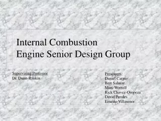
Internal Combustion Engine Senior Design Group. Supervising Professor Dr. Dunn-Rankin. Presenters : Daniel Carpio Bert Salazar Marc Worrell Rick Chavez-Oropeza David Perales Ernesto Villasenor. The Goal.

E N D
Internal CombustionEngine Senior Design Group Supervising Professor Dr. Dunn-Rankin Presenters: Daniel Carpio Bert Salazar Marc Worrell Rick Chavez-Oropeza David Perales Ernesto Villasenor
The Goal • Design and build a working internal combustion engine laboratory. The engine is to be controlled by the user to run tests and analysis for different load and engine parameter cases. • The steps in the process include the following: • The engine’s electronics will be rewired to eliminate any unnecessary electrical connections. • The IC engine’s original factory computer will be bypassed with a newly reconfigured chip. • A throttle position device will be designed to the control the throttle electronically. • A dynamometer will be installed to run load tests on the engine.
December October November January Rewire Engine EECU and ignition system Troubleshooting engine wiring harness and ignition system Engine Running with its own computer and wiring harness Attempt Lean Burn Condition with Hydrogen injection March April February May Determine viability between OPTO22 vs. Our own algorithm Troubleshooting closed loop control system IC Engine Presentation Closed Loop PC Control initiated PD Throttle position linkage employed Time Line of Events • This table illustrates the time it will take to perform each step.
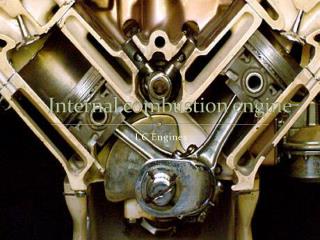
Basic Components Engine Stand Wiring Harness Engine
Basic Components (cont..) Radiator and Fan Fuel Tank Housing
Throttle Position Control • An adapter plate will be designed and fabricated to change the position of the throttle body on the engine. • The plate will enable the fitting of an electric motor to control the position of the throttle. • An electric circuit will be designed to control the motor, thus controlling the throttle position. Original Throttle Plate
Throttle Position Control (cont.) • The throttle plate will attach the throttle body to the original surface on the engine. • The throttle shaft will have the exact dimensions of the original except for at the top, where a motor will be attached to the end of it. Original Shaft Fabricated Shaft Where throttle shaft is inserted Throttle Shaft Throttle Body
Throttle Position Control (cont.) Motor Adapter Plate Throttle Shaft 3-D Rendering of Entire Position Control
Wiring Panel • Rewire original wire harness removing unnecessary wiring. • Replace prototype wire board with a new, easier one to use. • Provide a separation point in wiring to facilitate a quick change of control devices. Original Wiring Harness Unused Wiring
Wiring Panel (cont.) • This board will be replaced with a new encased metal switch panel. Battery Engine Wire Connector Strip Fuse Box Original On-board Computer Wiring Board (prototype) Ignition Switch
Control Chip Progress • It has been determined that OPTO-22 was inadequate for our control needs. • Controllers with required speed and flexibility have been researched. • The input and output required by the engine has been identified and the general operating scheme by which the existing factory controller functions has been determined. • The controller board search has been narrowed to four potential candidates. All of the controllers are available through Tern. (www.tern.com) • The current and voltage requirements of the inputs and outputs must now be found so that one controller may be chosen.
Dynamometer • Unit has been purchased. Delivery is expected during the fifth week of instruction. • A stand will be built for the installation of the dynamometer. • The Dynamometer will be used to provide performance and power curves for various engine test parameters. Actual Dynamometer Unit