Download
1 / 18
190 likes | 465 Vues
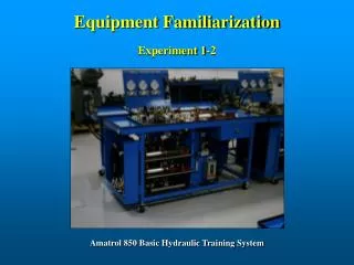
Equipment Familiarization. Experiment 1-2. Amatrol 850 Basic Hydraulic Training System. Equipment Familiarization. Objectives. 1. Identify each of the components in the 850 basic hydraulics system. 2. Set up the 850 basic hydraulics system bench. (Satellite will not be used).

E N D
Equipment Familiarization Experiment 1-2 Amatrol 850 Basic Hydraulic Training System
Equipment Familiarization Objectives 1. Identify each of the components in the 850 basic hydraulics system. 2. Set up the 850 basic hydraulics system bench. (Satellite will not be used) 3. Prepare the hydraulic power unit for use. 4. Operate a hydraulic power circuit. 5. Set up and operate a basic hydraulic circuit on the 850 trainer.
Equipment Familiarization The 850 system includes both Hydraulic as well as Pneumatic training equipment with the majority of focus given to the hydraulic trainer. The bench itself is mainly for storage, holding additional components, and to house the power unit. Earlier models located the power unit in a slightly different position. The modules may be moved where ever necessary and modules may even be used in pairs if needed. The benches roll but have been locked in place for safety reasons.
Inventory The loose components consist of Tee fittings, Male connectors, Friction shaft and Clamp, and a Load spring. Although the loose components should be kept on the machines, they do tend to stray off and therefore may necessitate locating as they may be found in different locations.
Valve Modules One of the most important features of the pneumatic valve module is its transparent valve assemblies. Transparent components allow for internal inspection without the need of disassembly. Another difference is that the pneumatic valve module includes the actuators whereas the hydraulic module does not. The pneumatic module has a directional control valve, 2 check valves, single acting cylinder, a pair of cylinders, and a motor. The hydraulic module has one Directional Control Valve(DCV), a pair of check valves, a single needle valve without a check, and a pair of pressure control valves.
Equipment Familiarization As can be seen from the illustration above, the primary function of the bench is to serve as a storage facility for the modules, provide a surface on which circuits may be constructed, and to house the power unit.
Instrumentation Modules The instrumentation modules are very similar but there exists some differences worth noting. The pneumatic instrumentation module has a pressure control valve whereas the hydraulic module does not. Also, the pneumatic module has a second pressure measurement tool used to observe very low pressures. Each of the modules uses a flow meter, the pneumatic meter measure air flow in standard cubic feet of air per hour(SCFH), and the hydraulic meter in gallons per minute(GPM).
Hydraulic Actuator Module The hydraulic actuator module has the same type of cylinders as the pneumatic module does. It also has a pair of flow control valves, with bypass checks, and a hydraulic motor which may or may not have a flywheel attached. Its important to remember that there may be some difficulty encountered when attempting to install or remove the flywheel. Under no circumstances should the flywheel be forced on or off the shaft. Always consult the instructor if a problem is encountered.
Loose Components Each of the trainers was originally equipped with about eleven hoses, 3 Tee fittings, 2 Male connectors, a Flywheel for the motor, an Extension piece for the friction shaft, a Friction shaft, a Clamping device for the friction shaft(not shown on page 7), and a Load spring. There have been many additions to the loose components. If what you need is not located on your machine, check the drawers of the other machines for the components.
Hydraulic Power Unit Inspection Refer to Video One The power unit supplied with the trainers were designed for intermittent use only. Before startup, make sure that the stop button is in the OFF position, the oil level is above the RED line, the Pressure is at minimum setting, and the power cord is unplugged. Also, the yellow valve should be in the DOWN position. If the unit fails any of these checks, report it to the instructor immediately.
Hydraulic Power Unit Inspection Make sure the power is off. Plug in cord after checking the controller. Always be certain that the power unit will not start the moment you plug in the power cord.
Startup and Shutdown Procedures Startup • Perform Inspection of power unit. • Assemble circuit. • Start power unit and adjust pressure to specifications. • Open yellow valve. • Operate circuit and record readings. Shutdown • Reduce pressure to minimum. • Shut off power unit. • Cycle any DCV in the circuit. • Close the yellow valve. • Disassemble circuit. • Clean up machine, modules, hoses, and area.
Power Unit Start Up Notice that on start up, even before the pressure is adjusted, that some pressure develops on the pressure gauge.
Connecting Circuits Connecting circuits is easy and very fast thanks to the quick connect feature of the hoses. Although this is not the industry standard, it suits our purpose well because breaking fittings loose is time consuming and would take away from the overall lab experience. Connections should never be made while the machine is running and this is consistent with OHSA lock out-tag out. If difficulty is encountered while attempting to make a connection, make sure that the machine is off and that the lines are not under pressure. Any oil spills should be cleaned up immediately.
Connecting Circuits You will notice that a little oil leaks out of the connectors every time they are disconnected and this is normal. This minor leakage
Basic Circuit Demonstration This video is a demonstration on the setup of a basic circuit that uses a double acting cylinder.
General Safety • Observe all safety precautions. • Be conscience of where your hands are at all times. • Always wear safety glasses in the lab. • Read all instructions before you attempt to work on the equipment. • Respect pressurized fluids as you would any energy form. • Keep an eye on the people around you.
Review 1. Which piece of the training equipment is for storage? 2. What is the safe maximum operating pressure of the 850 trainer? 3. Explain the startup and shutdown procedures. 4. What does it mean if a connection cannot be made? 5. How should you find the power cord prior to start up? 6. What must be done at the end of lab each day, immediately following the last experiment? 7. Describe the setting of the pressure control valve on startup. 8. Are the power units on the 850 trainer designed for continuous duty? 9. Why doesn’t oil pour out of the hoses when they are disconnected? 10. How is pressure determined at the power unit?