Chapter 2 2D sketch drawing
301 likes | 507 Vues
Learn essential skills for 2D sketching, including geometry, dimensions, and constraints. Explore various commands to draw base geometries like lines, rectangles, circles, arcs, fillets, and splines. Discover practical tips and tricks to streamline your sketching process effectively.

Chapter 2 2D sketch drawing
E N D
Presentation Transcript
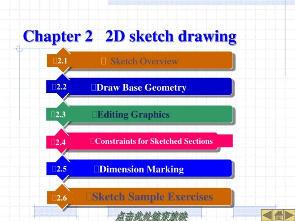
Sketch Sample Exercises • Editing Graphics • Sketch Overview • Draw BaseGeometry • Constraints for Sketched Sections • Dimension Marking • 2.3 • 2.2 • 2.1 • 2.5 • 2.6 • 2.4 Chapter 2 2D sketch drawing
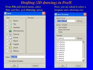
2.1 Sketch Overview • There are two ways to enter the sketch mode: ( 1 ) Switch into 3D modeling; ( 2 ) Create a new sketch file separately. • Sketch the three major features of a section: 2D geometry, dimensions, and constraints. • Sketch Idea: Draw the approximate shape of 2D geometry, dimension and modify to the correct dimension value, and then the system will automatically modify the geometry according to the dimension value.
2.1.1 Sketch Mode Sketch Figure 2-1 Sketch work interface
2.1.2 Practical Skills • 1. The use of the mouse • Left key: select objects, draw geometry, etc. Middle key: confirm, end or cancel the command and switch to selection mode; Right key: switch the selection of objects or pop up a shortcut menu. • 2. Selection of entities • Switch to selection mode first, then click the entity object with the left key. To select more than one object at a time, you can click with the left key box or press CTRL. If there are multiple overlapping objects in a certain position, you can right-click to switch between pre-selected objects. Endpoint 0:Straight line Endpoint 1:Straight line Circle (Construct) Figure 2-5 Right click mouse to switch preselect object
2.1.2 Practical Skills • 3. General steps and techniques of sketching ( trilogy ) • ( 1 ) Shape in Place: Draw the general shape of the section and make necessary edits. • ( 2 ) Dimensions and constraints in place: Specify constraints for geometry, including dimensioning and adding constraints. • ( 3 ) Dimension value in place: modify the values of all dimensions to design values and regenerate them ( usually by delaying modification ). • Skills: Try to make each section generated separately concise and easy to do. Complex sections can be broken down into separate and simple sections and be drawn in turn.
2.2 Draw Base Geometry • 2.2.1 Straight line • Select [ Sketch ] → [ Line ] or the icon button, and there are four ways to draw a straight line: Line (L) Line (L) Straight line tangent (T) Rectangular (E) Center line (C) Circle(C) Arc(A) Centerline Tangent (R) Figure 2-6 Four types of commands and tools to draw straight line Figure 2-7 Straight line tangent Figure 2-8 Center line tangent
2.2.2 Rectangle Figure 2-10 Draw a rectangular
2.2.3 Circle • There are five ways to draw a circle: Circle (C) Center and point (P) Arc (A) Concentric (C) Fillet (F) 3 Tangency (T) Chamfer (H) 3 Points (O) Spline (S) Axis end points ellipse (S) Center and Axis ellipse (E) Coordinate (O) Figure 2-11 Five commandstodrawacircleandtools Figure 2-12 Three ways to draw circles structural circle Click on the reference arc (b) Concentric (a) Circle Center and point (c) Concentric Figure 2-13 Draw an ellipse Figure 2-13 Draw a structural circle Figure 2-12 Three ways to draw circles
2.2.4 Circular Arc • There are five kinds of arc sketching methods: 3 points/tangent end (P) Arc (A) Concentric (C) Fillet (F) 3 tangent Spline (S) Coordinate (O) Circle center and end point(E) Point (P) Cone (N) Figure 2-15 Five commands and tools to draw an arc Create ‘3 points’ quadrant The existing geometric The endpoint of an existing arc 3. Circle point 2. End point 1. Start point (a) 3 points to draw a radian (b) Tangent ends to draw an arc Create ‘tangent arc’ quadrant Figure 2-16 3 points tangent end to draw an arc Figure 2-17 3 points arc/tangent end switching Figure 2-18 Concentric to draw an arc Figure 2-20 Circle center and end points to draw an arc Figure 2-19 Tangent arc drawing Figure 2-21Influence of Radius of Curvature rho on Absolute Conical Curve
2.2.5 Fillet • There are two forms of fillets, circular fillets and elliptical fillets. The two methods are the same, but the dimensions are different in form. • The geometric line of circular fillet is circular arc, and only one radius value R is needed to control it. The geometric line of the elliptical fillet is an elliptical arc, which needs to be controlled by two radius values Rx and Ry. (a) Round fillet (b) Ellipse fillet Figure 2-22 Two types of fillets
2.2.6 Spline Curve • Spline curve refers to a curve described by a polynomial of order 3 or more, which is formed by smoothly connecting a series of points. When drawing, select [ Sketch ] → [ Spline ] command or click the button, then use the left key to specify the position of each node in turn, and finally click the middle mouse button to finish. Figure 2-23 Draw a spline
2.2.7 Sketch points and sketch coordinate systems • Create Sketch Point: Select [Sketch] → [Point] or click the button. It is often used to assist in dimensioning or to control the pitch position of spiral scanning features. • Create Sketch Coordinate System: Select Sketch → Coordinate System or click the button, which is mainly used to assist geometry positioning or create position references for features. The positive X - axis direction of the sketched coordinate system is horizontally to the right, the positive Y - axis direction is vertically upward, and the positive Z - axis direction is toward the user.
2.2.8 Text • Select [Sketch] → [Text ...] or click the button, and you need to specify two points to draw a structural line to define the height and orientation of the text. Text Text structure line Text line Textual character… Font Figure 2-24 Text height and orientation Font Position Horizontal Left Vertical Bottom Length-width ratio oblique angle Place along curve Figure 2-25 Text dialog box Figure 2-26 Place text along the curve
2.3 Editing Graphics • 2.3.1 Delete • When editing graphics, generally select the object to edit (shown in red) first, and then select the corresponding editing command. When selecting entity objects, press CTRL to select multiple objects at the same time. • There are two ways to delete an operation: • (1) Select the [Edit] → [Delete] command or press the DEL key directly, and then select the section geometry to delete; (2) Select the geometric object to delete first, then choose [Edit] → [Delete] or press the DEL key.
2.3.2 Trim • The [ Trim ] command includes three forms, namely, delete segment, corner, and divide. • [ Delete Segment ] also known as " Dynamic Pruning", works in a similar way to the wiping movement of an eraser and can continuously select unwanted segments to delete. • Corner is used to trim the selected two geometric entities to their intersection points. • Split is used to generate breakpoints at the specified positions ( selection points ) of section entities. Trim line (S) Trim (T) Corner (C) Switching structure (G) Segment Figure 2-27 Trim command options and icons Delete unwanted line segment Select the wanted line to keep Figure 2-28 Delete segment trimming Figure 2-29 Corner trimming
2.3.3 Copy and Paste • Copy is used to copy sketched geometry while scaling and rotating the copied entities. It is required to select the geometric entity (s) to be copied first and click the menu command [Copy], then click the menu command [Paste] and specify a placement location. Pan and size adjustment Rotating mark Pan Panning mark Ref. H/V Orthogonal/vertical Rotate/Scale Scaling mark Reference Rotate Scale Figure 2-30 Sketch duplicating Figure 2-30 Pan and zoom adjustment dialog box
2.3.4 Mirror • Mirror the selected geometry to the other side of the specified centerline and automatically add symmetry constraints. It is required to have a center line as the axis of the mirror image. • When operating, first select the geometric object to be mirrored, then select the command [Edit] → [Mirror] or the icon button, and then select a center line as the mirror axis. Figure 2-32 Mirror command in symmetric application
2.3.5 Move and Adjust Largeness • Select [Edit] → [Scale and Rotate] or click the icon button to zoom and rotate the sketch drawing. Figure 2-33 Sketch pan and adjustment
2.3.6 Switching Structure • Select [Edit] → [Toggle Construction] command to switch the selected primitive object between geometry and construction graph. • When operating, first select the geometry object to be switched (multiple), and then select the Toggle Construction command.
2.3.7 Use Edges and Offset Edges • If you have feature geometric edges that can be referenced when sketching a section, you can choose the Use and Offset commands or click the Sketch Tool button. • Using the [ Use ] command, you can project the edges of the selected model onto the sketch plane to create section geometry; With the Offset command, the edges of the selected model can be projected onto the sketch plane and offset relative to it to create section geometry. Use (U) Edge (G) Offset (O) Data from file (F)… Thicken (T) Dimension (D) Figure 2-35 Use edge and offset command option and icon Figure 2-36 Use edge sketch Figure 2-37 Sketch offset
2.3.8 Dynamic Modification • In sketch mode, you can use the left mouse button to drag the geometry of the section directly to realize the dynamic modification of the shape. However, the modification effect of geometry is also different depending on the location of the mouse selection point. Dynamic drag to adjust round Click the round Click center Dynamic drag the center Figure 2-38 Select radius and drag to adjust size Figure 2-39 select center of circle drag to the position
2.4 Constraints for sketched sections • 2.4.1 Types of constraints • 1.Constraint types and their functional descriptions Table 2-3 Button of Constrain types and function explanations Icon description Button Name Function description Function description Define line or two-point line vertically Align Define point coincidence, point on line, or collinear Vertical Horizontal Defines the symmetry of two points about the centerline Symmetric Define line or two-point line horizontally Equal Perpendicular Define two-pixel orthogonality Define equal length, equal radius, or equal curvature Defines two lines parallel parallel Tangency Define two-pixel tangency Center Point Define the point at line center
2.4 Constraints for sketched sections • 2.4.1 Types of constraints • 2. Constraint symbols of different constraint types in the section • In Pro / E, each constraint type has its own specific symbol mark. Figure 2-40 Vertical constraint symbol Figure 2-41 Horizontal constraint symbol Figure 2-42 Orthogonal constraint symbol Figure 2-43 Tangent constraint symbol Figure 2-44 Midpoint constraint symbol Figure 2-42 Align constraint symbol Figure 2-47 Equal constraint symbol Figure 2-46 Symmetric constraint symbol Figure 2-48 Parallel constraint symbol
2.4.2 Create Constraints • Select Sketch → Constraint or icon button, then click the corresponding button in the Constraints dialog box and specify the geometric object to be constrained to add the constraint. • Vertical: simply click on the sketched line or two graphic endpoints to be constrained; • Horizontal: simply click on the sketched line or two graphic endpoints to be constrained; • Orthogonal: click the two entities to be constrained in turn; • Tangency: click the two geometric entities to be constrained in turn; • Midpoint: Select the point ( or end point ) to be constrained and the line in turn; • Alignment: when two constraint points coincide, a point is located on a specified entity or two lines are collinear, you need to click on the two entity objects to be constrained in sequence; • Symmetry: Select the center line and two points ( or endpoints ) to be symmetrical in turn; • Equal: Constrain the two straight lines to be equal in length or the radii ( or curvatures ) of the two arcs are equal; • Parallel: Constrain two lines to be parallel to each other. Figure 2-49 Constraint Tool box
2.5 Dimension Marking • The dimensions automatically marked by the system are usually gray (weak dimensions) and often do not meet the design requirements, so you must manually add dimensions and change their values. • The basic operation of dimensioning: Click the geometric object to be dimensioned with the left key, and then click the middle key to place the dimension at the appropriate position. Specific dimensioning types are: • [ Normal ]: Label the geometry and position of the section drawing ( parametrically driven ). • Reference: Label reference dimension ( non - parametrically driven ). • [ Baseline ]: Baseline for labeling polar coordinates. • [ Perimeter ]: Label the perimeter of the continuous line in the section drawing. Dimension (D) Long (N) Constrain (C) Perimeter (P) Reference (R) Baseline (B) Explanation (E) Option Figure 2-63 Types of dimension marking
Sketch → Dimension → Normal command. • 1. Linear dimensions • ① Length of a single line segment: Left click to select the line segment or the two end points of the line segment, and middle click to place the size. • ② Distance between two lines: Left - click to select two parallel lines and click the middle key to place the dimension. • ③ Distance between two points: Left - click to select two designated points and click the middle key to place the size. • ④ Distance from point to line: Left click to select the specified line and point in turn, and click the middle key to place the dimension. • ⑤ Line - to - circle distance: mark the distance between the line and the center of the circle; Or the tangent distance from the dimension line to the circumference. • ⑥ Distance between two circles: Click on the center of the two circles to mark the distance between the centers of the two circles; Click on the circumference of two circles to dimension the vertical or horizontal tangent distance dimension. • 2.5.1 Vertical Dimensioning (a) Horizontal or vertical dimensions (b) Parallel Dimension Figure 2-65 Dimension between two points Figure 2-68 Dimension of tangent distance between two Circles
2.5.1 Vertical Dimensioning • 2. Radial dimensions • Left - click the circle dimension radius and double-click the dimension diameter. The dimension position depends on the placement of the middle key. • 3. Symmetric dimensions • There must be a center line as the center axis of the rotation feature. Click the mark object, center line, mark object, and then click the middle key to place the dimension. • 4. Angular dimensions • Mark the included angle between two straight lines: click two straight lines with the left key and then place the dimension with the middle key; Mark the center angle of the circular arc: click the circular arc and the two end points of the circular arc in sequence, and then place the dimension with the middle key. 4. Select centerline 4. Placement Dimension 2. Select centerline 1.Select the arc 3. Placement Dimension 1. Selection dimension line 3. Then select the dimension line 2. Select centerline 1,2Select two straight lines (b) Circular arc angle (a) Angle between two straight lines Figure 2-71 Mark angle dimensions Figure 2-70 Mark symmetric dimensions
2.6.2 Example of Sketch Section Figure 2-94 Sketching sample 2
2.6.2 Sketch Section Example 2 • Step 1: Create a new sketch section file • Step 2 Draw the geometry of the section and edit it to the desired shape • Step 3 Dimension and Add Constraints • Step 4: Modify each dimension to the design value and regenerate it • Step 5 Sketch the internal shape of the section Sketch point Figure 2-95 Add sketching points to the section Figure 2-97 Dimensioning of sections Figure 2-98 Add radius equality constrains