Understanding Direct Current (DC) Circuits: Concepts, Applications, and Homework Assignments
This chapter focuses on Direct Current (DC) circuits, covering critical concepts such as electromotive force, resistors in series and parallel, and Kirchhoff’s rules. Students will analyze circuits containing batteries, resistors, and capacitors, developing a solid foundation in electric circuit analysis. The chapter includes essential homework assignments due on specific dates to reinforce learning, alongside practical examples involving current flow, voltage drops, and resistor configurations. In addition, the material contrasts DC with Alternating Current (AC), paving the way for future discussions.

Understanding Direct Current (DC) Circuits: Concepts, Applications, and Homework Assignments
E N D
Presentation Transcript
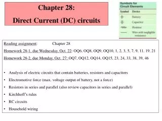
Chapter 28: Direct Current (DC) circuits • Reading assignment: Chapter 28 • Homework 28-1, due Wednesday, Oct. 22: OQ6, OQ8, OQ9, OQ10, 1, 2, 3, 5, 7, 9, 11, 19, 21 • Homework 28-2, due Monday, Oct. 27: OQ7, OQ12, OQ14, OQ15, 23, 24, 33, 38, 39, 46 • Analysis of electric circuits that contain batteries, resistors and capacitors • Electromotive force (max. voltage output of battery, not a force) • Resistors in series and parallel (also review capacitors in series and parallel) • Kirchhoff’s rules • RC circuits • Household wiring
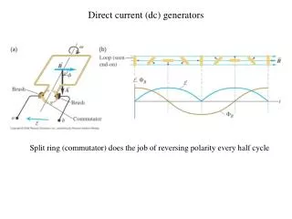
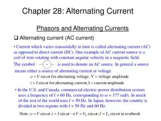
I0 Current Current Time Time -I0 Direct current (DC) and Alternating current (AC) • When a battery is connected to a circuit, the current flows steadily in one direction. This is called direct current or DC. (In RC circuits, current increases/decays over time, but still only flows in one direction). • Electric generators at power plants produce alternating current or AC. That is what comes out of an outlet. We will look at AC current in chapter 33.
Resistors in series* (Two devices are connected in series if they are connected at one end, and nothing else is connected there) *Same current flows through all devices; if one device breaks, current flow to all is interrupted. Different voltage drops.
Resistors in parallel* Two devices are in parallel if they are connected at both ends *Same voltage drop across all devices ; current gets split up.
White board example i-clicker. Series and parallel resistors. Two resistors (R1 = 50 W; R2 = 150 W ) are connected (a) in series and (b) in parallel to a 24 V battery (see Figure). What is the equivalent resistance of each circuit; what is the voltage drop across each resistor, what current runs through each resistor and the entire circuit? I1 R1 37.5 W 50 W 100 W 150 W 200 W 37.5 W 50 W 100 W 150 W 200 W
500 W 700 W White board example Series with parallel in circuit. How much current, I, flows from the battery shown in the figure? How much current, I1 flows through the 500 W resistor? • The current I flows out of the battery. • Passes through 400-Wresistor. • Splits into I1 and I2 and passes through the 500 Wand 700 W resistor. • I1 and I2 combine, I runs back to battery. • Charge carriers arrive with 0V at battery, get lifted up to 12V and start again.
Two i-clickers. The brightness of a light bulb is proportional to the current running through bulb. The circuit has three identical light bulbs each with resistance R. When the switch is closed how will the brightness of bulbs A and B compare with C? What happens when the switch is opened? A S C All the same B is brighter than C C is brighter than A and B B and C are the same brightness A and B are brighter than C B
Electromotive Force (EMF) and Terminal Voltage • A device such as a battery or a generator that transforms one type of energy (chemical, mechanical) into electric energy is called a seat or source of electromotive force or emf. • The potential difference between the terminals of such a device, when no current flows to an external force, is called the emf of the source. • Symbol is • Each battery itself has a resistance that is called internal resistance; it is designated r. • When no current is drawn from the battery the voltage between the terminals equals the emf. • If current is drawn from the battery, there is an internal voltage drop equal to Ir. Thus the terminal voltage (voltage delivered) is Vab = - Ir = r = 6 V
Ideal vs. Non-Ideal Batteries 30 V 10 – + 50 • Up until now, we’ve treated a battery as if it produced a fixed voltage, no matter what we demand of it. • Real batteries also have internal resistance, r. • It limits the current and therefore the power that can be delivered. • If the internal resistancer is small compared to other resistances in the problem, we can ignore it. • The maximum potential difference E across the battery is called electromotive force (emf) • The voltage output is DV = e - Ir i-clicker A 30 V battery with internal resistance, r = 10 , is connected to a resistor R (load) of 50 . What is the actual voltageDV across the 50 resistor? 30 V 36 V 6 V 25 V 24 V
White board example Analyzing a circuit. A 9.0-V battery whose internal resistance r is 0.5 W is connected in the circuit as shown in the figure. How much current is drawn from the battery? What is the terminal voltage (output voltage) of the battery? What is the current in the 6.0-Wresistor?
– I1 + I2 – + I3 Kirchhoff’s Rules 1. Rule (junction rule) At any junction point, the sum of all currents entering the junction must be equal to the sum of all currents leaving the junction (Conservation of charge). 12 V • How to apply it: • First, assign a current and a direction to every pathway • Two components in series will always have the same current • At every junction, write the equation: 3 B A 5 6 V 4 i-clicker. Which equation do you get for point A? A) I1 + I2 = I3 B) I2 + I3 = I1 C) I1 + I3 = I2 D) I1 + I2 + I3 = 0
– I1 + I2 – + I3 Kirchhoff’s Rules 2. Rule (loop rule) The sum of the changes in potential around any closed path of a circuit must be zero. (Conservation of energy). 12 V • How to apply it: • First, assign a direction to every loop • I often pick clockwise • Start anywhere, and set 0 equal to sum of potential change from each piece: • For batteries: V = E • It is an increase if you go from – to + • It is a decrease if you go from + to – • For resistors: V = IR • It is a decrease if you go with the current • It is an increase if you go against the current 3 5 6 V 4 Example: Set up the equations for loop 1 and loop 2. What are currents I1, I2, I3?
When applying Kirchhoff’s rules: • Label + and - for each battery. The long side of a battery symbol is +. • Label the current in each branch in the circuit with a symbol and an arrow (direction). The direction of the arrow can be chosen arbitrarily. If the current is actually in the opposite direction, it will come out with a minus sign in the solution. • Apply Kirchhoff’s junction rule at each junction, the loop rule at one or more loops. (Need as many equations as there are unknowns; possibly need more equations since some may be redundant.) • When applying the loop rule, follow each loop in one direction only (either clockwise or counterclockwise). Pay attention to signs: • For a resistor, the sign of the potential difference is negative if your choosen loop direction is the same as the chosen current direction through that resistor; the sign is positive if you are moving opposite to the chosen current direction. • For a battery, the sign of the potential difference is positive if your loop direction moves from the negative terminal toward the positive terminal; the sign will be negative if you are moving from the positive terminal toward the negative terminal. • Solve the equations for the unknowns. Be careful not to err with signs. At the end check your answers by plugging them into the original equations.
Consider loop at left: (start at point a (or point e)) Vab = - IR1 = - 6.96 V I = 0.0174 A Vbc = - IR2 = - 5.04 V 6.96 V Vde= + 12 V 5.04 V Sum of all voltages: - 6.96 V - 5.04 V + 12V = 0
White board example: Solving problems with Kirchhoff’s rules: Using Kirchhoff’s rules. Calculate the currents I1, I2, I3 in each of the branches of the circuit in the Figure. We have three unknowns --> We need three equations. - + - + Use Maple, a powerful Math program to solve equation set for us: solve({I3 = I1+I2, -30*I1+45-41*I3 = 0, 41*I3+21*I2-125 = 0}, {I1, I2, I3});
EMFs in series and in parallel Connecting the emfs in series head-to-tail, the voltages add up. Vtotal = V1 + V2. (b) Connecting the emfs in series tail-to-tail or head-to-head, the voltages subtract Vtotal = V1 - V2. Can be used for re-charging batteries. (c) Connecting emfs in parallel. Used to provide energy when large amounts of current are needed (starting Diesel engines).
Quick aside: Circuits containing capacitors in series and in parallel (‘inverse’ laws as compared to resistors)
Circuits containing a resistor and a capacitor (RC circuits) (Still DC current in one direction, but changes over time (decreases, increases). Charging a capacitor: Charging and discharging a capacitor Time constant: RC (units: second) Large RC: slow charging In t = RC seconds capacitor reaches 63% full voltage Discharging a capacitor: Time constant: RC (units: second) Large RC: slow discharging In t = RC seconds voltage falls to 37% (100%-63%)
Circuits containing a resistor and a capacitor (RC circuits) (Still DC current in one direction, but changes over time (decreases, increases). Discharging a capacitor: Time constant: RC (units: second) Large RC: slow discharging In t = RC seconds voltage falls to 37% (100%-63%)
Circuits containing a resistor and a capacitor (RC circuits) (Still DC current in one direction, but changes over time (decreases, increases). Charging a capacitor: Time constant: RC (units: second) Large RC: slow discharging In t = RC seconds voltage falls to 37% (100%-63%)
White board example An RC circuit. If a capacitor with capacitance, C = 35 mF, is connected to a resistor with resistance, R = 120 W, how much time will elapse until the voltage falls to 10 percent of its original (maximum) value?
Electric shock • The severity of an electric shock depends on the magnitude of the current, how long it acts and through what part of the body it passes. • Can feel ~ 1 mA; pain at a few mA; severe contractions above 10 mA; heart muscle irregularities above 70 mA. • Current above 100 mA for only a few seconds can be fatal. • Resistance of dry skin ~ 104 to 106W; wet skin 103W or less. • A person in good contact with ground who touches a 120 V line with wet hands can suffer a current
Power in Household circuits (All appliances are connected in parallel Fuses: • Electrical wires in a household can get too hot, if they are not thick enough for the amount of current running through them. • This is a fire hazard. • To avoid this danger, circuit breakers (fuses) are installed, which break the circuit if the current running through a wire is too high (e. g. above 20 A). • Wires of varying thickness are connected to different circuit breakers (thick wires are needed to carry high currents). Resistance of a wire
Light bulb: 0.8 A Heater: 15.0 A Stereo: 2.9 A hair dryer: 10.0 A Total: 28.7 A Black board example Will the fuse blow? Determine the total current drawn by the devices in the circuit shown in the Figure. A 20 A fuse would blow
Electrical safety, two-pronged, three-pronged wires Two pronged wire: One is ‘hot’ or ‘live’; the other carries current to ground. If the “hot” wire touches the metal casing of an appliance, it becomes “hot” and simply touching the metal case can result in shock. • Three pronged wire: One wire is ‘hot’ or ‘live’ (narrower slit);the other carries current to ground (wider slit). • Grounding the metal case through the third wire (round prong) • metal case is always grounded and no shock can occur.
Review • Resistors in series • Resistors in parallel • Know how to apply these rules to circuits • Electromotive power and internal resistance • Kirchhoff’s rules (Know how to apply to a circuit): 1. Rule (junction rule) At any junction point, the sum of all currents entering the junction must be equal the sum of all currents leaving the junction. (Conservation of charge). 2. Rule (loop rule) The sum of the changes in potential around any closed path of a circuit must be zero. (Conservation of energy). • RC circuits, time constant t = RC • A bit of house hold wiring (circuits with appliances in parallel and a circuit breaker in series; electrical safety.