Understanding Computer Interrupts and Peripheral Component Interconnect (PCI) Bus Technology
240 likes | 415 Vues
This overview explains the fundamental components of a personal computer, focusing on how hardware interrupts work and the role of the Peripheral Component Interconnect (PCI) bus. When you press a key, like "A", a signal is sent that interrupts the CPU's current task, prompting it to execute an appropriate interrupt service routine (ISR). This efficient handling of tasks contrasts with polling methods, making interrupts vital for managing requests. The PCI bus enables the connection of various components, allowing for upgrades and improved performance in modern computers.

Understanding Computer Interrupts and Peripheral Component Interconnect (PCI) Bus Technology
E N D
Presentation Transcript
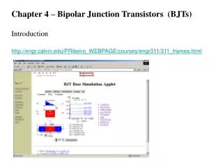
Plug ‘n Play, Semiconductors, Bits and Transistors Dr. Harold D. Camp IT 212 002 8 February 2007
Components of a Normal PC • http://computer.howstuffworks.com/pci.htm
Press the “A” Key • When you press the A key • An electrical signal travels along a circuit • Identifies what key you pressed • The keyboard interrupt arrives on one of 16 interrupt request (IRQ) lines • Seven of the IRQs monitor specific components, such as the keyboard controller • The controller relays a signal to a subsystem called the interrupt controller • Runs interference between the CPU and 256 possible kinds of interrupts. • The other interrupt circuits keep an eye on the input/output bus • Includes the computer's expansion slots • More than one expansion card on the Peripheral Component Interconnect (PCI) and PCI-Express slots use the same IRQ • The requests are managed by the Plug 'n' Play function • The interrupt controller sends a signal to the INTR pin • Sticks out of the bottom of the CPU • Used for normal interrupt signals • There's also an pin NMI, for non-maskable interrupts • Such as the one generated by pressing Ctrl+Alt+Del
Press the “A”Key • The CPU puts whatever it was doing on hold • Memory address written to a stack. • To remind the CPU later where it left off from its previous task • Two methods of controlling the CPU: polling and interrupts. • Polling goes from task to task endlessly, asking if they need anything from the CPU • If a task needs something, the other tasks have to wait until that task was completed • Not very efficient • Interrupts, the CPU goes about her work until an external task issues an interrupt • The interruption gets immediate attention, at least until another external task needs something • Interrupts are the preferred method of handling requests from software and hardware • The CPU checks to find out what key you pressed • Rather than display the letter, the CPU checks the interrupt descriptor table (IDT). • The CPU performs the instructions at the IDT's locations associated with the A key • The CPU calls an interrupt service routine (IRS) to tell the CPU what to do when • Allows programmers to replace the normal instructions with another program • In a game, pressing the A key could make a character move left, W move up, and so on • When the IRS completes its job, the CPU executes a return from interrupt (RET) • Tells the CPU to return to whatever it was doing before it was interrupted • The CPU pulls the last memory location off the stack and processes the next instructions
Busses • Power and speed of computer components increased at a steady rate since desktop computers were first developed • Software makers create new applications capable of utilizing the latest advances in processor speed and hard drive capacity • Hardware makers rush to improve components and design new technologies to keep up with the demands of software • The bus • Essentially, a channel or path between the components in a computer • Having a high-speed bus important • Many different types of buses • We concentrate on the Peripheral Component Interconnect (PCI) bus • The idea of a bus is simple • Lets you connect components to the computer's CPU. • Hard disks, memory, sound systems, video systems and so on • For example, you need special hardware to drive the screen • The screen is driven by a graphics card • A small printed circuit board designed to plug into the bus
Bus Connections • A typical PC today has two main buses: • System or local bus • Connects the microprocessor (CPU) and the system memory • Fastest bus in the system • A slower bus for communicating with hard disks and sound cards • Connect to the system bus through a bridge, part of the computer's chipset • Acts as a traffic cop • A bus makes parts more interchangeable • If you want a better graphics card • Unplug the old card from the bus • Plug in a new one • If you want two monitors on your computer • Plug two graphics cards into the bus
PCI Bus • Along came PCI • Early 1990s, Intel introduced a new bus standard • Peripheral Component Interconnect (PCI) bus • A hybrid between ISA and VL-Bus • Direct access to system memory for connected devices • Uses a bridge to connect to the system bus and the CPU • Capable of even higher performance than VL-Bus and • Eliminates interference with the CPU • The system bus physically connects the processor to most of the other components in the computer • Including main memory (RAM), hard drives and PCI slots • The system bus usually operates at 400-MHz to 800-MHz. • There are other buses as well • Universal Serial Bus (USB) • Connects things like cameras, scanners and printers • A thin wire to connect to the devices • Many devices can share that wire simultaneously • Firewire is another bus • Used mostly for video cameras & external hard drives
Variety of Busses • Original PC bus (circa 1982) • 16 bits wide • Operated at 4.77 MHz • Known as the ISA bus • Data rate of up to 9 MBps (megabytes per second) • Fast enough for today's applications • ISA remained in use even after more advanced technologies were available • Long-term compatibility with a large number of hardware manufacturers • Before the rise of multimedia • Technology advanced and ISA failed to keep up • Extended Industry Standard Architecture (EISA) • 32 bits at 8 MHz • Vesa Local Bus (VL-Bus). • 32 bits wide and the speed of the system bus • Essentially tied directly into the CPU • Connecting more than two devices to the VL-Bus caused interference with CPU performance • VL-Bus was typically used only for connecting a graphics card
Backside Bus • The backside bus • A separate connection between the processor and the Level 2 cache • Operates faster than frontside bus • Same speed as the processor • Caching works efficiently as possible. • Backside buses evolved over years • In 1990s, backside bus was a wire • Connected CPU to an off-chip cache • Cache was a separate chip • Required expensive memory • Since then, the Level 2 cache is integrated into the microprocessor • Smaller and cheaper
Plug ‘n Play Bus • PCI connects more devices VL-Bus • Up to five external components • Each of the five connectors can handle two fixed devices on the motherboard • You can have more than one PCI bus on the same computer • PCI bridge chip regulates the speed of the PCI bus independently of the CPU • Provides higher reliability • Ensures PCI-hardware manufacturers know exactly what to design for. • PCI originally operated at 33 MHz using a 32-bit-wide path, revisions include • Increasing the speed from 33 MHz to 66 MHz • Doubling the bit count to 64 • PCI-X provides for 64-bit transfers at a speed of 133 MHz for an amazing 1-GBps • PCI cards use 47 pins to connect • Able to work with so few pins because of hardware multiplexing • Device sends more than one signal over a single pin • PCI supports devices that use either 5 volts or 3.3 volts. • Although Intel proposed the PCI standard in 1991 • Became popularity with Windows 95 (in 1995 • Windows 95 supported a feature called Plug and Play (PnP
What is Plug ‘n Play • With Plug and Play under Microsoft Windows Server 2003 • Connect a hardware device to your system • Leave the job of configuring and starting the device to the operating system • Plug and Play in Windows Server 2003 supports a wide range of devices • In Windows Server 2003 • Plug and Play support is optimized for computers that include an Advanced Configuration and Power Interface (ACPI) BIOS • Defined by Advanced Configuration and Power Interface (ACPI) Specification • Hardware and software interface specification • Combines and enhances Plug and Play and Advanced Power Management (APM) standards • ACPI devices include low-level system devices (batteries) • On x86-based computers • Interaction between the BIOS and Plug and Play depends on whether the system BIOS or the operating system configures the hardware • Plug and Play detection runs with logon process • Relies on system firmware, hardware, device drivers, and operating system features to detect and enumerate new devices • ACPI firmware provides enhanced features, such as hardware resource sharing • When Plug and Play components are coordinated, Windows Server 2003 can detect new devices, allocate system resources, and install or request drivers with minimal user intervention.
HyperTransport • A standard proposed by Advanced Micro Devices, Inc. • Touted by AMD as natural progression from PCI. • For each session between nodes, it provides two point-to-point links • Each link can be anywhere from 2 bits to 32 bits wide • Supports maximum transfer rate of 6.4 GB per second • Designed specifically for connecting internal computer components to each other • Not designed for connecting external devices • Development of bridge chips will enable PCI devices to access the HyperTransport bus
The Windows Registry • Every operating system and application needs a place to store configuration settings and user preferences • MS-DOS uses CONFIG.SYS • DOS programs had to make their own arrangements for storing user settings • Windows originally used INI files • Read and written using special routines available to Windows programs • Windows had one configuration file, SYSTEM.INI • Used for all the internal settings • Plus another, WIN.INI, for user preferences • Each application had an INI file • INI files were slow to access and limited to 64Kb • Unsuited for the 32-bit versions of Windows • So for Windows NT and Windows 95 Microsoft introduced the Registry • A database for storing and accessing configuration data • Organized for fast and efficient access • Data is stored in a hierarchical manner like the folders on a hard disk • Registry data that is currently in use is cached to provide better performance • http://www.tech-pro.net/intro_reg.html
Numbers, Computer Style 1 0 1 0 0 1 1 0 1 0 | - | - - | | - | - x o x o o x x o x o y n y n n y y n y n • 000, 001, (rightmost digit starts over, and next digit is incremented) • 010, 011, (rightmost two digits start over, and next digit is incremented) • 100, 101, ...
Binary Arithmetic • Addition • half adder, which adds two bits together, producing sum and carry bits • The simplest arithmetic operation in binary is addition. Adding two single-digit binary numbers is relatively simple: • 0 + 0 = 0 • 0 + 1 = 1 • 1 + 0 = 1 • 1 + 1 = 10 (carry:1) • Multiple bits • 1 1 1 1 1 (carry) • 0 1 1 0 1 • + 1 0 1 1 1 • ------------- • 1 0 0 1 0 0 • http://en.wikipedia.org/wiki/Binary_numeral_system#Binary_simplified
Transistor • Switch: On or Off • Record and Manipulate Numbers (base 2) • Transistor Circuits • Logic Gates • Half-Adders • Full Adders
How does a Transistor Work Junction Transistor
How does a Transistor Work Field Effect Transistor http://tech-www.informatik.uni-hamburg.de/applets/cmos/cmosdemo.html
Homework 3 Prepare a memory map for a PC with • 1 MByte RAM • 8 PCI devices • Each PCI device requires 8 memory locations