Device Management
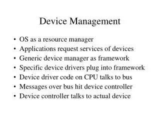
Device Management. 5. Input/Output Devices. Output Device. Processor. Input Device. The Device Driver Interface. … write(…); …. Device Interface. Terminal Driver. Printer Driver. Disk Driver. Terminal Controller. Printer Controller. Disk Controller.

Device Management
E N D
Presentation Transcript
Input/Output Devices Output Device Processor Input Device
The Device Driver Interface … write(…); … Device Interface Terminal Driver Printer Driver Disk Driver Terminal Controller Printer Controller Disk Controller
Device Management Organization Application Process System Interface File Manager Device-Independent Device-Dependent Hardware Interface Command Status Data Device Controller
System Call Interface • Functions available to application programs • Abstract all devices (and files) to a few interfaces • Make interfaces as similar as possible • Block vs character • Sequential vs direct access • Device driver implements functions (one entry point per API function)
Example: BSD UNIX Driver open Prepare dev for operation close No longer using the device ioctl Character dev specific info read Character dev input op write Character dev output op strategy Block dev input/output ops select Character dev check for data stop Discontinue a stream output op
Overlapping the Operation of a Device and the CPU . . . startRead(dev_I, “%d”, x); . . . While(stillReading()) ; y = f(x) . . . . . . read(dev_I, “%d”, x); y = f(x) . . . Data on device Variable x Register Device dev_I Memory CPU
Gantt Chart • A Gantt chart is a graphical representation of the duration of tasks against the progression of time. http://www.ganttchart.com/
Gantt Chart • Gantt charts are useful tools for planning and scheduling projects. • Gantt charts allow you to assess how long a project should take. • Gantt charts lay out the order in which tasks need to be carried out. • Gantt charts help manage the dependencies between tasks. • Gantt charts determine the resources needed.
Gantt Chart • Gantt charts are useful tools when a project is under way. • Gantt charts monitor progress. • You can immediately see what should have been achieved at a point in time. • Gantt charts allow you to see how remedial action may bring the project back on course.
Henry Laurence Gantt (1861-1919) was a mechanical engineer, management consultant and industry advisor. • Henry Laurence Gantt developed Gantt charts in the second decade of the 20th century. • Gantt charts were used as a visual tool to show scheduled and actual progress of projects. • Accepted as a commonplace project management tool today, it was an innovation of world-wide importance in the 1920s. • Gantt charts were used on large construction projects like the Hoover Dam started in 1931 and the interstate highway network started in 1956.
Henry Gantts contribution to the management process is honored today through the Henry Laurence Gantt Medal. • The award established in 1929 is given for distinguished achievement in management and for service to the community.
Overlapping CPU-Controller Operations in a Process App I/O Ctlr t1 t2 t3 t4 t5 t6 t7 t8 t9
Overlapping Processing and I/O App 1 App 2 I/O Ctlr t1 t2 t3 t4
I/O strategies • 1. Direct I/O with Polling. • 2. DMA I/O with Polling. • 3. Direct I/O with Interrupt. • 4. DMA I/O with Interrupt.
Polling I/O Read Operation read(device, …); 1 Data System Interface read function 5 write function 2 3 4 Hardware Interface Command Status Data Device Controller
Direct I/O with Polling (IN) • 1. The application process requires a read operation. • 2. The device driver queries the status register to determine if the device is idle, if the device is busy, the driver waits for it to be idle. • 3. The driver stores an input command into the controller’s command register, thereby, starting the device. • 4. The driver repeatedly reads the status register while waiting for the device to complete its operation. • 5. The driver copies the contents of the controller’s data register(s) into process’s space.
Direct I/O with Polling (OUT) • 1. Process requests an output operation. • 2. Driver status register, busy? Wait. • 3. Driver copies data from user space memory controller’s data registers. • 4. The driver stores an output command into the command register, thereby starting the device. • 5. The driver repeatedly reads the status register while waiting for the device to complete the operation.
Interrupt-driven I/O Operation read(device, …); 9 1 8b Data System Interface Device Status Table 4 7 Device Handler read driver 2 write driver 6 3 8a Interrupt Handler Hardware Interface 5 Command Status Data Device Controller
Interrupt Driven I/O Operation • 1. Process requests a read operation • 2. Top half of the driver queries the status register, idle? -> Yes! -> Wait! • 3. If no longer busy, the driver stores command into the controller’s command register and thereby starting the device for read operation. • 4. When read driver completes its work, information regarding the op -> device status table.
Device Status Table contains an entry for each device in the system. • 5. Eventually, the driver completes the operation and interrupt the CPU and cause the interrupt handler to run. • 6. The interrupt handler determines which device caused the interrupt. It then branches to the device handler for that device. • 7. The device handler retrieves the pending I/O status information from the device status table. • 8. The device handler copies the contents of the controller’s data registers into the user process’s space (memory). • 9.The device handler-behaving as the bottom half of the device driver invoked by the application process-thus returns control to the application process.
Device Independent Function Call Trap Table funci(…) dev_func_i(devID, …) { // Processing common to all devices … switch(devID) { case dev0: dev0_func_i(…); break; case dev1: dev1_func_i(…); break; … case devM: devM_func_i(…); break; }; // Processing common to all devices … }
Driver-Kernel Interface • Drivers are distinct from main part of kernel • Kernel makes calls on specific functions, drivers implement them • Drivers use kernel functions for: • Device allocation • Resource (e.g., memory) allocation • Scheduling • etc. (varies from OS to OS)
Reconfigurable Device Drivers System call interface open(){…} read(){…} Entry Points for Device j etc. Other Kernel services Driver for Device j
Handling Interrupts Device driver J Device interrupt handler J Device status table int read(…) { // Prepare for I/O save_state(J); out dev# // Done (no return) } void dev_handler(…) { get_state(J); //Cleanup after op signal(dev[j]); return_from_sys_call(); } J Interrupt Handler Device Controller
Handling Interrupts(2) Device driver J Device interrupt handler J int read(…) { … out dev# // Return after interrupt wait(dev[J}); return_from_sys_call(); } void dev_handler(…) { //Cleanup after op signal(dev[j]); } Interrupt Handler Device Controller
The Pure Cycle Water Company Customer Office Water Company Returning the Empties Water Producer Water Consumers Delivering Water
Hardware Buffering Process Process Process Controller Controller Controller Data A B A B Device Device Device Process reads bi-1 Controller reads bi Process reads bi Controller reads bi+1 Unbuffered
Double Buffering in the Driver Process Process A B A B Driver Controller Controller A B A B Hardware Device Device
Circular Buffering To data consumer Buffer i Buffer j From data producer
A Generic Communications Device Bus Generic Controller Communications Controller Local Device Cabling connecting the controller to the device Device • Printer • Modem • Network
Rotating Media Cylinder (set of tracks) Track (Cylinder) Sector (a) Multi-surface Disk (b) Disk Surface (b) Cylinders
Storage Device Device Driver API • Driver • Get disk description • Set SCSI parms • read/write ops • Interrupt hander • SCSI API • commands • bits per byte • etc. Controller (SCSI) Magnetic Disk
Compute vs I/O Bound Compute-bound Time I/O-bound
Disk Optimizations • Transfer Time: Time to copy bits from disk surface to memory • Disk latency time: Rotational delay waiting for proper sector to rotate under R/W head • Disk seek time: Delay while R/W head moves to the destination track/cylinder • Access Time = seek + latency + transfer
Optimizing Seek Time • Multiprogramming on I/O-bound programs => set of processes waiting for disk • Seek time dominates access time => minimize seek time across the set • Tracks 0:99; Head at track 75, requests for 23, 87, 36, 93, 66 • FCFS: 52+ 64 + 51 + 57 + 27 = 251 steps
Optimizing Seek Time (cont) • Requests = 23, 87, 36, 93, 66 • SSTF: (75), 66, 87, 93, 36, 23 • 11 + 21 + 6 + 57 + 13 = 107 steps • Scan: (75), 87, 93, 99, 66, 36, 23 • 12 + 6 + 6 + 33 + 30 + 13 = 100 steps • Look: (75), 87, 93, 66, 36, 23 • 12 + 6 + 27 + 30 + 13 = 87 steps
Optimizing Seek Time (cont) • Requests = 23, 87, 36, 93, 66 • Circular Scan: (75), 87, 93, 99, 23, 36, 66 • 12 + 6 + 6 + home + 23 + 13 + 30 = 90 + home • Circular Look: (75), 87, 93, 23, 36, 66 • 12 + 6 + home + 23 + 13 + 30 = 84 + home
Serial Port CPU Memory Serial Device • Printer • Terminal • Modem • Mouse • etc.
UART • universal • asynchronous • receiver- • transmitter
Serial Port Device Driver API • Device Driver • Set UART parms • read/write ops • Interrupt hander Software on the CPU Bus Interface • UART API • parity • bits per byte • etc. Serial Device (UART) • RS-232 Interface • 9-pin connector • 4-wires • bit transmit/receive • ...
Adding a Modem CPU • Dialing & connecting • Convert analog voice to/from digital • Convert bytes to/from bit streams • Transmit/receive protocol Memory Serial Device Modem Phone Switched Telephone Network
Serial Communication • Device Driver • Set UART parms • read/write ops • Interrupt hander • Driver-Modem Protocol • Dialing & connecting • Convert analog voice to/from digital • Convert bytes to/from bit streams • Transmit/receive protocol Serial Device RS-232 Modem
Exploiting the Phone Network Logical Communication CPU CPU Memory Comm Device Comm Device Memory Modem Modem Phone Phone Switched Telephone Network
Data Networks • Technology focus includes protocols and software • (more on this later … Chapter 15 and beyond ...) Logical Communication CPU CPU Memory Network Device Network Device Memory Data Network
The USB Process • When the host powers up, it queries all of the devices connected to the bus and assigns each one an address. • This process is called enumeration -- devices are also enumerated when they connect to the bus. • The host also finds out from each device what type of data transfer it wishes to perform:
Interrupt - A device like a mouse or a keyboard, which will be sending very little data, would choose the interrupt mode. • Bulk - A device like a printer, which receives data in one big packet, uses the bulk transfer mode. A block of data is sent to the printer (in 64-byte chunks) and verified to make sure it is correct. • Isochronous - A streaming device (such as speakers) uses the isochronous mode. Data streams between the device and the host in real-time, and there is no error correction.