CIMExcel Software Inc. Slide 1
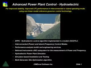
Advanced Power Plant Control - Hydroelectric For improved stability, improved LFC performance in interconnected or island operating mode, using non-linear model reference governor control technology. APPC - Hydroelectric control algorithm implemented in a modern DCS/PLC.

CIMExcel Software Inc. Slide 1
E N D
Presentation Transcript
Advanced Power Plant Control - Hydroelectric For improved stability, improved LFC performance in interconnected or island operating mode, using non-linear model reference governor control technology. • APPC - Hydroelectric control algorithm implemented in a modern DCS/PLC. • Interconnected (Power) and Island (Frequency) Control Modes. • Performance analysis toolkit and engineering services. • National Instruments cRIO subsystem for the measurement of Power and Frequency. • Hydroelectric Power Plant Simulator. • Simulator-based Installation and Testing. • Multi-Generator Site Optimization algorithm. CIMExcel Software Inc. Slide 1
Advanced Power Plant Control • for the following energy sources Nuclear Wind Hydroelectric Fossil Biomass/Solid Waste/Cogeneration Combined Cycle Gas Turbine CIMExcel Software Inc. Slide 2
APPC Hydro vs. Classic Control AGC-LFC Performance Comparison • APPC Hydroelectric • AGC (Power) Requirement: • 90% -> 40% in 10 seconds • 40% for 10 seconds • 40% -> 90% in 10 seconds • Power • Rotor Frequency • Turbine Head • Gate Positioner • APPC achieves the required AGC performance • performance error =∫ | e | dt = 0.8 pu-sec • Classic Control does not achieve the required AGC performance • performance error =∫ | e | dt = 4.0 pu-sec • Classic Control CIMExcel Software Inc. Slide 3
APPC Hydro vs. Classic Control AGC-LFC Performance Comparison • APPC Hydroelectric • AGC (Power) Requirement: • 10 second interval pulse train as shown • Power • Rotor Frequency • Turbine Head • Gate Positioner • APPC achieves the required AGC performance • performance error =∫ | e | dt = 0.3 pu-sec • Classic Control does not achieve the required AGC performance • performance error =∫ | e | dt = 6.25 pu-sec • Classic Control CIMExcel Software Inc. Slide 4
Technical Description APPC - Hydroelectric Hydroelectric Power Plant Modeling and Simulation APPC - Hydroelectric discrete-time, non-linear model reference control algorithm APPC - Hydro simulated Interconnected (Power) Mode Performance APPC - Hydro simulated Island (Frequency) Mode Performance Project Activities Simulator-based Installation and Testing Approach Design of Hydroelectric Power Plant Performance Tests Performance Analysis Toolkit NI cRIO-based Power-Frequency Measurement and Power Generation Observer Gate Positioner Response Analysis Turbine Characteristic Curves Generator Dynamic Response Island Mode Response Test National Instruments cRIO Configurations CIMExcel Software Inc. Slide 5
APPC - Hydroelectric: Modeling • Twc (5 - 50 s) • Ts (100 - 1000 s) • Twp (0.4 - 2.0 s) • Tg (0.2 - 0.5 s) • f0(0.1 - 0.2) • f1 (0.01 - 0.04) • f2 (0.04 - 0.1) • H (2 - 10 s) • Pmax (1.5 - 3) • De (10 - 30) • DL (0.5 – 1.5) • Tunnel: • d/dt Uc = (H0 + Zc - Hs - f2Uc2) / Twc • Surge Tank: • d/dt Zs= ( Uc - Ut) / Ts • Hs = Zs +f0|Us| Us • Penstock: • d/dt Ut= (r(Hs + Zp) - Ht - f1Ut2) / Twp • Gate Positioner: • d/dt GP = ( UP - GP) / Tg G = hysteresis(GP) • Turbine: • Ht*= (Ut/ g1(G))2 • Pm = UtHt* g2(G) = Ht*1.5 g3(G) • Generator (interconnected mode): • d/dt ωr= ( Pm - Pemax(sinδr + αsin2δr) - De(ωr- ωG) ) / 2 H • d/dt δr= ω0(ωr- ωG) • Generator (island mode): • d/dt ∆ωr= ( Pm - Pe0 - DL ∆ωr ) / 2 H • ∆ωr = ωr- ωrset CIMExcel Software Inc. Slide 6
1 1 1 + TPs 1 + TPs • Wicket Gate - Turbine - Generator Model • interconnected mode: Up Pm + Gp G ωr g3( ) ( )1.5 1/2Hs - + + Pd D - + Ht* δ ω0/s Pe Po(sin(δ) + α sin(2δ)) ωG • loop output - - positioner - - gate - - - - turbine - - - - - - - - - - - - - - generator • island mode: Up Pm + Gp G g3( ) ( )1.5 ωr 1/2Hs - + + DL - + Ht* Pe0 ω0 CIMExcel Software Inc. Slide 7
Discrete-time Non-linear Model Reference Control event driven Power Control Algorithm adaptive discrete time step size Pe set(j) Pe(j) Power Generation Observer interconnected mode ~ 5 seconds Pe(t) AGC G(j) Gu(j) P(j) Gu(t) Mode Selector Hysteresis Compensator ωr(t) ÷ g3-1() Smoother operator g4() Ht*1.5(j+1) island mode Frequency Control Algorithm Blade Hysteresis Compensator ωr set Hydroelectric Model Reference Predictor Smoother B(j) Bu(j) Bu(t) ωr(j) (with variable pitch blades) Filter/ Sampler Ht*(t) ωr(t) CIMExcel Software Inc. Slide 8
Classic Control - Load Frequency Control (conceptual) + ωrset filter ωr - deadband 1 Rp rate limits limits deadband τR S + 1 + + rate limits limits deadband load Up (RT/Rp)τR S + 1 droop, Rp = 0.05 transient, RT = 0.38 reset, τR = 1 s, interconnected = 5 s, island mode CIMExcel Software Inc. Slide 9
APPC - Hydroelectric - Interconnected Mode Performance • (moderate variation of AGC load allocation) CIMExcel Software Inc. Slide 10
APPC - Hydroelectric - Interconnected Mode Performance • (fast variation of AGC load allocation) CIMExcel Software Inc. Slide 11
APPC - Hydroelectric - Island Mode Performance • (external AGC triggered at 2% overgenerated) CIMExcel Software Inc. Slide 12
Performance Analysis and Engineering Services For Francis, Kaplan, Pelton turbines, surge tanks, and with modern DCS/PLCs. • Analysis • Data Acquisition System setup, interfacing to PLC, programming in PLC. • Power-Frequency measurement, signal analysis and filtering. • Analysis, modeling, and simulation of the tunnel, surge tank, and penstock. • Analysis, modeling, simulation of the governor system. • Design of the Performance Tests. • Testing • Testing for the penstock water hammer dynamics. • Testing for the wicket gate and blade pitch positioner hysteresis and response. • Testing for the characteristic curves for the turbine flow, power, and efficiency. • Testing for the generator dynamic response. • Baseline Performance monitoring and analysis for interconnected and island operation. • Simulator • Configuration for the Hydroelectric site and the APPC control algorithms. • Comparative simulation performance analysis of existing and APPC control algorithms. • Integration of the Hydroelectric Power Plant Simulator at the site. • Installation of the APPC control algorithms in the DCS/PLC • Parallel control loop block, bumpless transfer switch. • Function Block Configuration and or Structured Text Programming. Simulator-based testing. • Performance Trials and Acceptance Testing • Interconnected Mode - load following response. • Island Mode - frequency control response, and or simulated island operation. CIMExcel Software Inc. Slide 13
Simulator-based Installation and Testing DCS /PLC Turbine Head Turbine Flow Rotor Frequency Electric Power existing control loop Gate Positioner Turbine Head Turbine Flow Rotor Frequency Electric Power (PGO) APPC control loop Gate Positioner Turbine Head Turbine Flow Rotor Frequency Electric Power Hydroelectric Power Plant Simulator Gate Positioner Grid Frequency Rotor Frequency Generator 3 Phase Voltages Generator 3 Phase Currents NI DAQ / PAC Subsystem Electric Power (PGO) CIMExcel Software Inc. Slide 14
Performance Analysis Toolkit High Speed NI-DAQ Signal Processing and Filtering Time Series Analysis Fourier Analysis Power Spectral Analysis CIMExcel Software Inc. Slide 15
Power and Frequency Measurement - Power Generation Observer CIMExcel Software Inc. Slide 16
Gate Positioner Step Input Analysis Step Input without conditioning Step Input with conditioning CIMExcel Software Inc. Slide 17
Identification - Gate Positioner Hysteresis CIMExcel Software Inc. Slide 18
Characteristic Curves - Flow, Power, and Efficiency CIMExcel Software Inc. Slide 19
Island Mode Response Testing • (0.02 pu load reduction) 0.02 pu DL = 1 2H = 11.4 s CIMExcel Software Inc. Slide 20
National Instruments cRIO Controller • Power and Frequency Measurement Configuration NI cRIO Controller with LabVIEW- IEC 1131 Software Rotor Frequency Phase 1 Voltage Phase 1 Current Phase 2 Voltage Phase 2 Current Phase 3 Voltage Phase 3 Current Power Generation Rotor Frequency CIMExcel Software Inc. Slide 21
National Instruments cRIO Controller • Identification Configuration Rotor Frequency Phase 1 Voltage Phase 1 Current Phase 2 Voltage Phase 2 Current Phase 3 Voltage Phase 3 Current Turbine Head Turbine Flow Gate Positioner Output NI cRIO Controller with LabVIEW- IEC 1131 Software Power Generation Rotor Frequency Gate Positioner Input PC with APPC - Hydroelectric Software CIMExcel Software Inc. Slide 22
National Instruments cRIO Controller • Simulator Configuration NI cRIO Controller with LabVIEW- IEC 1131 Software Phase 1 Voltage Phase 1 Current Phase 2 Voltage Phase 2 Current Phase 3 Voltage Phase 3 Current Gate Positioner Output* Power Generation Rotor Frequency Turbine Head Power Generation Rotor Frequency Turbine Head Grid Frequency Gate Positioner Output* PC with APPC - Hydroelectric Software CIMExcel Software Inc. Slide 23