Download
1 / 27
270 likes | 396 Vues
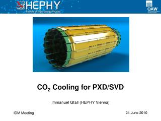
CO 2 Cooling for the Atlas-IBL. Auke-Pieter Colijn Krista De Roo Bart Verlaat Gertjan Mul Martijn Van Overbeek Erno Roeland Piet de Groen Luc Jansen Martin Van Beruzekom NIKHEF Amsterdam February 2009. Atlas-IBL CO 2 cooling Contents. Introduction to the 2PACL system

E N D
CO2 Cooling for the Atlas-IBL Auke-Pieter Colijn Krista De Roo Bart Verlaat Gertjan Mul Martijn Van Overbeek Erno Roeland Piet de Groen Luc Jansen Martin Van Beruzekom NIKHEF Amsterdam February 2009 02-02-2009
Atlas-IBL CO2 coolingContents • Introduction to the 2PACL system • IBL-cooling tube calculations • CO2 tube routing in Atlas • CO2 cooling prototyping 02-02-2009
Introduction to CO2 cooling • CO2 cooling for the IBL relies on the successful heritage of the VELO Thermal Control System in LHCb. • Power and temperature range of the IBL is similar => A copy of the VTCS can almost be made. • The VTCS works according to the 2PACL method, developed originally for the AMS tracker CO2 cooling, and successfully scaled up for the VELO cooling. 02-02-2009
2PACL principle ideal for detector cooling: Liquid overflow => no mass flow control Low vapor quality => good heat transfer No local evaporator control, evaporator is passive in detector Very stable evaporator temperature control with 2-phase accumulator (P4-5 = P7) The 2-Phase Accumulator Controlled Loop (2PACL) Long distance P4-5 P7 5 Heat out Heat out Condenser 6 Heat in 4 Heat in 2 3 evaporator Heat exchanger 1 2-Phase Accumulator Restrictor Pump Vapor Liquid Pressure 2 3 2-phase 4 P7 5 1 6 02-02-2009 Enthalpy
LHCb-VTCS Overview(VELO Thermal Control System) Accessible and a friendly environment Inaccessible and a hostile environment 2.6 m PLC 3.6 m 4m thick concrete shielding wall 2 Evaporators 800 Watt max per detector half 2 CO2 2PACL’s: 1 for each detector half 2 R507A Chillers: 1 water cooled 1 air cooled 2 Concentric transfer lines 55 m 02-02-2009 VELO
March ’08: Commisioning of the VTCSDetector under vacuum and unpowered 02-02-2009
2PACL in Atlas-IBL facts: • Cold fluid transfer, needs isolation • Only 1 tube (Concentric in and outlet), with isolation (~ø70mm) • No heaters in detector: Complete passive! • Very stable temperature control: <0.05°C • Large operational temperature range: • -30°C to +20°C (-30°C can be lowered to -40°C when changing to CO2 chilling) 02-02-2009
IBL cooling design philosophy: 150 Watt 150 Watt 800mm 800mm System A System B 150 Watt 75 Watt 75 Watt • Fully redundant cooling of the IBL • -Two cooling pipes per stave, each connected to an individual cooling system. • Design cooling tube on half the power. • A failure of maintenance of 1 cooling system is not catastrophic, staves can be kept cold. • Cooling of a powered detector with 1 system is most likely possible due to included safety margins. 02-02-2009
Temperature (ºC) Pressure (Bar) Tube inner diameter (mm) DCO2≈1.4 mm DC3F8≈3.6 mm IBL stave cooling tube sizing (1) • Traditional method: • Calculating dP & dT according to the Friedel correlation • - Set threshold for max. temperature gradient • IBL stave assumptions: • 800 mm long • 150 Watt power (Non redundant) • -25ºC cooling fluid temperature • 40% exit vapor quality dP according to Friedel 02-02-2009
IBL stave cooling tube sizing (2) • IBL stave assumptions: • 800 mm long • 150 Watt power (Non redundant) • -25ºC cooling fluid temperature • 40% exit vapor quality DCO2 = 1.4 mm DC3F8 = 3.6 mm Temperature distribution (ºC) Heat Transfer coefficient (W/m2K) Tube wall Heat transfer according to Kandlikar Fluid Tube length (m) Tube length (m) 02-02-2009
Kandlikar IBL stave cooling tube sizing (3) Nowadays more fancy design tools are available: And guess, they do not comply at all! (Welcome in the magic world of 2-phase flow!) Corresponding zone Results of the 1.4 mm CO2 tube in the Thome flow pattern maps Thome predicts an early dry-out 02-02-2009
IBL stave cooling tube sizing (4) Redundant stave (2 cooling tubes) 1.4mm ID Stave with 1 single cooling tube 2.1mm ID 02-02-2009
Are these spikes from a LHCb VELO test the dry-out which Thome predicts? 02-02-2009
Evaporator tube sizing conclusion: • Pressure drop is no problem • (0.6 bar Friedel, 0.4 bar Thome) for 1.4mmID @ 150 Watt • HTC needs testing, 2-phase flow HTC predictions too unsure. • 1.4mmID tube fits for both theories, but is critical for dry out in single tube stave design. 1.5mmID tube is chosen for testing. 02-02-2009
Multiple or single outlet tube? Hand bended 2.5x0.25 mm soft stainless tube 1.9 mm ID (single tube stave). 2.4 mm ID (Double tube stave) Outlet capillaries should be flexible “they can be treaded as a cable” Single outlet tube is stiff and pre-shaped Outlet capillaries diameter Single outlet tube diameter 3/8”x0.035” (single tube stave). “1/4”x0.035” (Double tube stave) 02-02-2009
Capillary and outlet tube sizing Assumption: DpCapillary>10xDpoutlet dP outlet (Bar ) dP capillary (Bar ) dP (Bar) 0.5°C dT (°C ) D=0.2.38 mm D=0.1.85 mm dT outlet (°C ) D=0.88 mm D=0.68 mm Diameter (mm) Single tube stave 1.28 g/s (150 Watt) Redundant tube stave 0.64 g/s (75 Watt) 02-02-2009
IBL tube summary * standard orbital weld size • As connectors cannot be fitted inside the barrel: • Multiple outlet tubes are connected to the staves at all time during assembly • But, staves are single units • A manifold inside the barrel makes a very complex assembly scheme, as single staves are connected permanently together. 02-02-2009
CO 2 Inner dry volume boundary IBL Capillary manifold Outer dry volume boundary IBL-CO2 cooling tube routing To PP2 sector 13 02-02-2009 bverlaat@nikhef.nl
CO 2 Dry volume on end plate Empty cable tray Muon chamber passage Magnet coil PP2-Sector 13 Joining concentric with vapor line from the other side Follow cable channels to find a way out to USA-15 IBL-CO2 cooling tube routing 02-02-2009 bverlaat@nikhef.nl
2-phase return line Protective cover 25mm Armaflex NH Isolation Ø13mm Ø16mm Ø66mm Sub-cooled liquid feed line Ø4mm Ø6mm IBL-CO2 Concentric Transfer Line In a 2-phase flow the main pressure drop is due to upward flow. IBL Static height of liquid : ~8m in USA => ΔT=0.8°C with CO2 (CO2≈0.1°C/m, C3F8 ≈ 2.3°C/m) 0 ~100m USA Cooling plant ~8m LHCb-VELO Transfer tube (Inlet liquid inside outlet 2-phase flow) 02-02-2009
Cooling plant space Freon Unit CO2 Unit PLC LHCb VELO cooling plant 02-02-2009
IBL CO2 cooling prototype CO2 2PACL PLC Accumulator Condenser Proto type cooler under construction Haake cryostat Pumps Primary cooler Pump unit detail 02-02-2009
Back-up slides or questions? 02-02-2009
CO 2 VTCS 2PACL Operation From start-up to cold operation (1) + 2 Pump head pressure (Bar) 2 4-Accumulator liquid level (vol %) 7 4 - Accumulator pressure (Bar) 7 5 – Evaporator temperature (°C) 4 1 Pumped liquid temperature (°C) 1 4- Accumulator Control: + = Heating - = Cooling 7 _ 7 -7 4 7 +7 2 02-02-2009 1 time A C B D 24 Start-up in ~2 hours
24 June ’08: After a succesful commisioning of the detector at -25°C, the setpoint is increased to -5°C.And has been running since then smoothly! 80 (3 sept 08) Accu Heating/Cooling 60 Accu level 40 Detector half heat load (x10) Module Heat load 20 Temperature (°C), Power (Watt), Level (vol %) 0 Silicon temperature -7°C SP=-5°C -20 Evaporator temperature SP=-25°C -40 1:30 0 1:00 2:00 0:30 02-02-2009 Time (Hour)
CO 2 LHCb-VTCS Cooling Components VTCS Evaporator Accumulators Valves Pumps Condensers 02-02-2009