Download
1 / 43
470 likes | 768 Vues
Nanoelectronic Devices based on Silicon MOS structure. Prof.C.K.Sarkar IEEE distinguish lecturer Dept of Electronics and Telecommunication Engineering Jadavpur University Kolkata- 700032. FUNDAMENTALS OF NANOTECHNOLOGY.

E N D
Nanoelectronic Devices based on Silicon MOS structure Prof.C.K.Sarkar IEEE distinguish lecturer Dept of Electronics and Telecommunication Engineering Jadavpur University Kolkata- 700032.
FUNDAMENTALS OF NANOTECHNOLOGY • Nanotechnology explores and benefit from quantum phenomenology in the ultimate limit of miniaturization. • At length-scales comparable to atoms and molecules, quantum effects strongly modify properties of matter like “color”, reactivity, magnetic or dipolar moment, … Besides, phenomena characteristic of systems with low dimensionality can be use to control macroscopic properties. • Leading Research efforts in Nanotechnology • Quantum confinement • Electronic Transport • Quantum confinement
Nanoparticles • What Is Nanocrystalline Silicon? • It is similar to amorphous silicon (a-Si) • It consists solely of crystalline silicon grains, separated by grain boundaries • Nanocrystalline silicon (nc-Si) is an allotropic form of silicon • Advantages of nanosilicon over Silicon • It can have a higher mobility due to the presence of the silicon crystallites. • Higher dielectric constant than bulk silicon. • One of the most important advantages of nanocrystalline silicon, however, is that it has increased stability over a-Si • Mainly used in optoelectronics due to direct band gap.
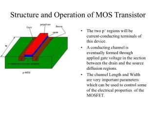
nc-Si Embedded MOS structure • This model consists of Si substrate/ pure SiO2/ Embedded nc-Si layer/ Gate electrode • Voltage applied at the gate Terminal • Electrons tunnel from Si-substrate to gate through these dielectrics. Gate Metal nc- Si Layer
Methodology to be adopted and Innovative aspects • Effective dielectric constant • Effective barrier height • Effective mass • Modification of tunneling probability
Maxwell – Garnett Effective medium Approximation theory • Inclusion particles randomly dispersed in dielectric medium • Silicon nanocrystallites spherical in shape.
Maxwell Garnett Theory embedded systems In a binary composite, if the density of silicon nanocrystals is small, each particle of the component can be treated as being embedded in a large medium of SiO2.
Mathematical formulation • The effective dielectric function of the composite could be expressed as =Screening factor depends upon the size and orientation of particle. For spherical it is 2 . fa = volume fill fraction of the particle
Tunneling in the model • Low Applied Gate voltage Direct tunneling • High Applied Gate voltage Fowler-Nordheim tunneling
Direct Tunneling At low field when V< The barrier becomes Trapezoidal in Shape.
Direct tunneling Expression From Simmon’s model modified at low field Where α = unit less adjustable parameter depends on effective mass and barrier height.
Fowler – Nordheim Tunneling At high field when V> The barrier becomes triangular in shape
Different conditions for Fowler – Nordheim equation For this condition qFeffd< Фb-E0 Tunneling probability Where V(x) = -qFs.x x<0
For this condition Фb-E0< qFeffd< Ф-E0 Tunneling probability becomes where V(x)=Фb-qFeff x 0<x<d
Observation • FN tunneling current increases • FN onset voltage decreases • Field emission starts at the low applied voltage. plot of I g-Vg curve for 30 nm thickness for both pure SiO2 and proposed dielectric.
b a The plot of ln(JFN/F2) vs. volume fraction at different applied voltages a) 5v b) 10v and c) 15v c
Direct Tunneling current density FN Tunneling current probability Tunneling current density
Carbon Nanotubes The Carbon nanotube • Electronic structure of Carbon nanotube • The geometry of Carbon nanotube • Electronic properties of carbon nanotube • Quantum Modeling & Proposed Design of CNT-Embedded Nanoscale MOSFETs • CNT band structure and electron affinity • CNT mobility model • Carrier concentration • Effective potential due to CNT-Si barrier
Electronic structure of Carbon nanotube • a single atomic layer of graphite consists of 2-D honeycomb structure • it has conducting states at, but only at specific points along certain directions in momentum space at the corners of the first Brillouin zone • Choosing different axes it can be used as typical metal or semiconductor
The geometry of Carbon nanotube ** The lattice constant a= |a1| = |a2| =3ac-c Where ac-c is carbon carbon bond length ** The vector describe the circumference of a nanotube Ch = na1 + ma2 **The chiral angle = sin-1{3m / 2(n2+m2+mn)}
Different types of carbon nanotubes • The construction of a nanotube through the rolling up of a graphene sheet leads to three direct verities • These are armchair nanotubes which have = 30o • These have an indices of the form (n,n)[n = m]. • For = 0o zigzag nanotube • The indices of the form (n,0) • For 00 < < 300chiral nanotube • Indices of the form (n, m)
From graphene to carbon nanotube • The only discrete wave-vectors are allowed in radical direction and the following condition is Ch . k = 2q • For an armchair nanotube the circumferential axis lies along x direction, |Ch| |kx| = 2q kx = 2q / 3na • For a zigzag nanotube the azimuthal direction lies along the y direction. |Ch| |kx| = 2q kx = 2q / na
Electronic property the nanotube is metallic or not can be described by the m and n indices with the following rule n = m metallic n – m = 3j metallic n – m 3j semiconducting
Dependence of semiconducting band gap with diameter The energy gap of semiconducting single walled nanotubes is predicted to be inversely proportional to the diameter of the nanotube The best fit equation is of the form is Eg = 2oac-c / d o = 2.25 0.06eV is a good arrangement shows a fundamental energy gap 0.4 – 0.9 eV which lie in the infrared range
CNT-Embedded Nanoscale MOSFETs New design a methodology has been developed for modeling nanoscale CNT-MOS-FETs
Fabrication Procedure • Thin HfAlO film was deposited on the Si substrate by the laser molecular beam epitaxy (MBE) • The ratio of Hf to Al for the ceramic target is 1:2 • The commercial CNTs were synthesized by chemical vapor deposition • The diameter and length are about 2 nm and 1.5µm respectively. • Finally another layer of HfAlO was deposited to cover these CNTs and form the structure of HfAlO/CNT/HfAlO/Si.
Pt/8nmHfAlO/CNT/3nmHfAlO/Si IV measured at 77K Actual structure
Nanotube Parameters The dielectric constant of CNT is dependent on its symmetry and tube radius Where C~ 1.96 For metallic 2.15 For Semiconducting According to Maxwell- Garnett Theory the effective dielectric constant can be written as Where f is the volume fraction and εox is the dielectric constant of HfAlO εox =16
C-V measurement of Embedded Carbon Nanotubes • Backward C-V curve overlaps forward C-V curve without CNT • A clear hysteresis between subsequent forward and backward C-V curves containing CNTs. • This curve suggests small number of charge carriers are stored inside CNTs. Typical C-V hysteresis characteristics of the CNT based MOS memory devices
Observation • Gate leakage current is direct tunneling current • Two different dielectric, pure HfAlO and HfAlO embedded with SWCNTs. • As gate voltages increases tunneling current density decreases. • Tunneling current is lower in embedded CNTs than pure HfAlO dielectric. • SWCNTs stored charges, breaks tunneling paths from channel to gate and current density decreases. Direct tunneling gate leakage current density at low gate voltage
Observations • Field emission or F-N tunneling current as a function of applied gate voltage. • The F-N tunneling onset voltage is lower in CNT embedded dielectric than pure HfAlO oxide dielectric F-N Tunneling current as a function of high gate voltages
Observation • F-N plot is straight line. • Slopes of the two different dielectrics pure and embedded are different • For a particular applied field the F-N tunneling current density is higher in CNT embedded dielectric than pure HfAlO oxide dielectric. • The dielectric constant is higher in CNT embedded dielectric than pure HfAlO dielectric F-N plot of pure HfAlO and CNT embedded HfAlO dielectric
Observation • Gate leakage current is direct tunneling current • As applied voltage increases tunneling current decreases • As the diameter of nanotube decreases direct tunneling current decreases. Direct tunneling current with different nanotube diameters
Observation • F-N tunneling current with different diameters of nanotubes • The F-N tunneling onset voltage decreases with the increase of the nanotube diameter. • The diameter in nanometer regime can cause a highly localized field across the nanotube surface. This helps to increase the Field emission current. F-N Tunneling current with the variation of nanotube diameters
Observation • High positive gate voltage • nc-Si embedded in SiO2 matrix • SWCNT embedded in high-k dielectric • High-k dielectric is HfAlO • F-N onset voltage is maximum in case of pure SiO2 and minimum in case of embedded CNTs in HfAlO • Embedded CNTs have better Field emission properties than embedded nc-Si. • Embedded CNT has highest dielectric constant. F-N tunneling current of different pure and embedded dielectric
Observation • F-N tunneling current higher in embedded dielectric than pure oxide • Tunneling current in embedded CNTs is higher than in embedded nc-Si • The value of dielectric constant is higher in HfAlO than Pure SiO2 • Tunneling current increases with the increase of dielectric constant value. F-N plot with different pure and embedded dielectrics
Observation • F-N onset voltage is highest in case of pure SiO2 • Onset voltage decreases with the introduction of nanoparticles. • Onset voltage is lower in case of CNT than in nc_si.
Observation • Leakage current is lower in high-k dielectric HfO2, than pure SiO2 • With embedded nanoparticles direct tunneling current also decreases • It is lowest in Hf)2 embedded with CNTs • All this is due to the higher value of dielectric constant of gate oxide
Conclusion • CNT-MOSFET device appears to yield better performance than the conventional MOSFET • The current voltage characteristics predicts that the device current of CNT-MOSFET is higher than the conventional one. • The narrow diameter tube shows similar performance compared to conventional one. • CNT-MOSFET may represent the new paradigm for devices in the 21st century