Z Transform
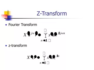
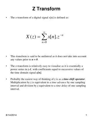
Z Transform. The z-transform of a digital signal x[n] is defined as: This transform is said to be unilateral as it does not take into account any values prior to n = 0 .

Z Transform
E N D
Presentation Transcript
Z Transform • The z-transform of a digital signal x[n] is defined as: • This transform is said to be unilateral as it does not take into account any values prior to n = 0. • The z-transform is relatively easy to visualise as it is essentially a power series in z-1, with coefficients equal to successive values of the time domain signal x[n]. • Probably the easiest way of thinking of z is as a time-shift operator. Multiplication by z is equivalent to a time advance by one sampling interval and division by z equivalent to a time delay of one sampling interval.
Find the z transform of the exponentially decaying signal shown below, expressing it as compactly as possible
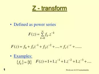
Geometric Progression • and from the sum to infinity of a geometric series which is given by: • and only if: • where a is them first term and r is the common ration • However, the sum of first n terms is given by: • For example: Find the sum of the first 8 terms of the following series and the sum to infinity: 8, 4, 2, 1 • a =8, r = 0.5
As far as DSP is concerned, one of the most important is the convolution property, which states that time domain convolution is equivalent to frequency-domain multiplication. e.g Which produces the following output sample. In the frequency domain, we can describe the signal by their z-transforms. The transforms of x[n] and h[n] are: X(z) = 1 – 2z-1 + 3z-2 -z-3 - z-4 and H(z) = 1 – z-1 – z-2 Where H(z) is known as the transfer function of the processor. The product of X(z).H(z) is X(z).H(z) = 2 – 3z-1 + 3z-2 + 3z-3 + 6z-4 - z-6 The corresponding signal has sample values equal to the coefficients of the power series, namely: 2 -3 3 3 -6 0 1 0 0 …. This confirms the result obtained by time domain convolution.
z-Plane Poles and Zeros • A z-transform used to describe a real digital signal can always be written as a ratio of numerator and denominator polynomials in z: • This is true whether X(z) represents an input or an output signal, or the transfer function of a processor. • The constants z1, z2 and z3 are called the zeros of X(z), because they are the values of z for which X(z) is zero. • Conversely p1, p2, and p are known as the poles of X(z), giving values of z for which X(z) tends to infinity. • A useful representation of a z-transform is obtained by plotting its poles and zeros on an Argand diagram. The plane is then referred to as the z-plane.
A useful representation of a z-transform is obtained by plotting its poles and zeros on an Argand diagram. The plane is then referred to as the z-plane. • On a pole-zero diagram any pole placed outside the unit circle is an area of instability, where the amplitude of the signal will increase with time. • The angle made by the pole vector with the positive real axis represents the signal frequency. • The length of the pole vector tells us how quickly the signal is decaying or increasing. The shorter the vector the more rapid the decay rate. If the length of the pole vector is 0.5 this indicates that the signal should fall to half it’s previous value every sampling period.
The signal moves round the perimeter of the circle anticlockwise • As the signal moves round the circle the frequency increases • The start of the circle 0° is 0Hz or DC • Once round the circle 360° indicates the Sampling frequency • Half way round the circle 180° is the Nyquist frequency
Gain = • Important points: • For system or signal stability the poles must lie inside the unit circle in the z-plane. • This restriction does not apply to zeros – they can be placed anywhere in the z-plane.
Example. If we have a discrete system with a transfer function given by and we need to find the response at dc (0 Hz), 1Hz and 2Hz, give that the sampling frequency is 8Hz. The pole-zero diagram is shown below. As the sampling frequency is 8HZ, the Nyquist frequency is 4Hz and so the three frequencies of 0, 1Hz and 2Hz must correspond to points A, B and C respectively.
Solution • At frequency = 0Hz • Phase angle = S zero angles - S pole angles • Phase angle = 0 – 0 = 0° • At frequency = 1Hz: The pole and zero distances are more difficult to calculate, hence it is probably easier to use a scale diagram and measure the distances.They approximate to BZ = 1.84 and BP = 0.73 • Gain = 1.84/0.73 = 2.5 • The angles approximate to tan-1 (0.7/1.7) = 22.3º and the pole angle = tan-1 (0.7/0.2) = 74.1º • Therefore Phase angle = 22.3° – 74.1º = -51.8° • At frequency = 2Hz: Here the zero distance is and the pole distance is Therefore Gain = = 1.27
The zero angle is 45º, and the pole angle is {180° – tan-1(1/0.5) = 116.5º}. Therefore the phase angle is 45° – 116.5º = -71.5°
There has to be a method of defining the effective end of the passband. This point is chosen as the ‘-3db point’. This is the frequency at which the gain has fallen by 3db, or to of its maximum value gain in db = 20 log10(gain) 20 log10 = -0.3010
http://www.earlevel.com/Digital%20Audio/PoleZero.html • Example 1 A lowpass digital filter is required that has a d.c. gain of 1 and a cut-off frequency which is 0.25 of the sampling frequency. The filter is to have a transfer function of the form T(z) = k(z + a)/(z + b) • Solution 1 The first task is to select a suitable zero and pole. To complete the design then the calculation of k is required.As a lowpass filter is required, then, after the initial passband, the gain must fall as the frequency increases, i.e. moving round the z-plane unit circle in an anticlockwise direction, starting at z = 1 (d.c). Now: Gain = As we want the gain to be close to zero at the Nyquist frequency, then a filter zero will need to be placed at z = -1. In order to achieve the desired response, the single pole probably needs to be placed somewhere on the positive real axis, i.e. this will ensure a large gain for low frequencies and a lower gain for high frequencies. Figure 6 shows the zero at z = -1 and the pole at z = d. Point A corresponds to 0Hz and point B to the cut-off frequency, which is half the Nyquist frequency (a quarter of the sampling frequency) Using Gain =
The gains at 0Hz and 0.5fN are given by: GainA = and GainB = But B is the -3dB point
Therefore the pole must be placed at the origin Applying Gain = At point A Substituting the a-, b- and k- values into the transfer function gives:
Question • A digital filter has a transfer function of 3(z – 0.5)(z +1)/z2 + 0.25). Find the frequency response at 0Hz, and 2.5Hz by (a)using a pole-zero diagram and (b) directly from the transfer function. The sampling frequency is 10Hz. Solution(a) This system has zeros at 0.5 and -1 and poles at . For zeros for poles The pole-zero diagram is shown in the diagram below:
= 2.4 • f = 0Hz Phase angle = S zero angles - S pole angles Phase angle = 0 + 0 – tan-10.5 – (360° - tan-10.5º) = 360° or 0º. • f = 2.5Hz: from the diagram below
Example. Plot the z-plane poles and zeros of the following z transform. The zeros are given by the values in the numerator i.e. The poles are the values in the denominator:
Zeros = 1.2, -1 and 0 Poles =0.5 – j0.7, 0.5 + j0.7 and 0.8 Important points: For system or signal stability the poles must lie inside the unit circle in the z-plane. This restriction does not apply to zeros – they can be placed anywhere in the z-plane. Zeros (or poles) at the origin of the z plane produce a pure time advance (or delay), but have no other effect on the characteristics of the processor or signal.