Download
1 / 38
380 likes | 498 Vues
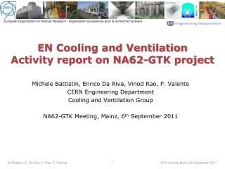
EN Cooling and Ventilation Activity report on NA62-GTK project. Michele Battistin, Enrico Da Riva, Vinod Rao, P. Valente CERN Engineering Department Cooling and Ventilation Group NA62-GTK Meeting, Mainz, 6 th September 2011. Agenda. CFD simulation on Microchannel solution for GTK

E N D
EN Cooling and Ventilation Activity report on NA62-GTK project • Michele Battistin, Enrico Da Riva, Vinod Rao, P. Valente • CERN Engineering Department • Cooling and Ventilation Group • NA62-GTK Meeting, Mainz, 6th September 2011 M. Battistin, E. Da Riva, V. Rao, P. Valente
Agenda • CFD simulation on Microchannel solution for GTK • Cooling unit engineering specification M. Battistin, E. Da Riva, V. Rao, P. Valente
GTK Microchannel Cooling - CFD Analysis for Hydraulic Design - M. Battistin, E. Da Riva, V. Rao, P. Valente
Summary • A) Silicon Microchannel C6F14 Heat Exchanger • Present prototype (Design-0) • Analytical model for pressure drop • CFD model and validation against experimental data • Performance of present prototype (Design-0) • Performance of double inlet/outlet (Design-1) • B) General Design Guidelines • Influence of channel geometry • Possible alternative refrigerants M. Battistin, E. Da Riva, V. Rao, P. Valente
Summary • A) Silicon Microchannel C6F14 Heat Exchanger • Present prototype (Design-0) • Analytical model for pressure drop • CFD model and validation against experimental data • Performance of present prototype (Design-0) • Performance of double inlet/outlet (Design-1) • B) General Design Guidelines • Influence of channel geometry • Possible alternative refrigerants M. Battistin, E. Da Riva, V. Rao, P. Valente
Present prototype (Design-0) • Refrigerant C6F14, temperature = -25°C • Max inlet/outlet temperature rise = 5 K • Heat load = 48 W • cp = 975 J kg-1 K-1 Mass flow rate 9.8 g/s • The dominating thermal constraint is considered the in/out refrigerant temperature rise and not the HTC achieved inside the microchannels A first prototype has been manufactured and tested by CERN PH/DT M. Battistin, E. Da Riva, V. Rao, P. Valente
Present prototype (Design-0) • The flow is laminar in the microchannels and turbulent in the manifold • Too high manifold velocity high pressure drop + maldistribution M. Battistin, E. Da Riva, V. Rao, P. Valente
Summary • A) Silicon Microchannel C6F14 Heat Exchanger • Present prototype (Design-0) • Analytical model for pressure drop • CFD model and validation against experimental data • Performance of present prototype (Design-0) • Performance of double inlet/outlet (Design-1) • B) General Design Guidelines • Influence of channel geometry • Possible alternative refrigerants M. Battistin, E. Da Riva, V. Rao, P. Valente
Analytical model • Most of the pressure drop is due to the manifold M. Battistin, E. Da Riva, V. Rao, P. Valente
Summary • A) Silicon Microchannel C6F14 Heat Exchanger • Present prototype (Design-0) • Analytical model for pressure drop • CFD model and validation against experimental data • Performance of present prototype (Design-0) • Performance of double inlet/outlet (Design-1) • B) General Design Guidelines • Influence of channel geometry • Possible alternative refrigerants M. Battistin, E. Da Riva, V. Rao, P. Valente
CFD model and validation • Mesh data ->No. of cells : 8.2 M Hexahedra: 8.1 Mpolyhedra: 0.1M ->Mesh non-orthogonality Max: 39.9 Average: 3.6 • The CFD model is able to predict experimental the data for the whole range of mass flow rates tested M. Battistin, E. Da Riva, V. Rao, P. Valente
Summary • A) Silicon Microchannel C6F14 Heat Exchanger • Present prototype (Design-0) • Analytical model for pressure drop • CFD model and validation against experimental data • Performance of present prototype (Design-0) • Performance of double inlet/outlet (Design-1) • B) General Design Guidelines • Influence of channel geometry • Possible alternative refrigerants M. Battistin, E. Da Riva, V. Rao, P. Valente
Performance of Design-0 • The refrigerant pressure drop predicted by the CFD model at design working conditions is 12.2 bar • This value could give rise to mechanical resistance problems • The Average mass flow rate in each channel is 0.03 g/sec • The distribution is not optimal • The channels close to outlet are fed with almost double the mass flow rate as compared to the ones close to the inlet • The temperature rise for the channels close to the inlet is expected to be higher then 5 K M. Battistin, E. Da Riva, V. Rao, P. Valente
Summary • A) Silicon Microchannel C6F14 Heat Exchanger • Present prototype (Design-0) • Analytical model for pressure drop • CFD model and validation against experimental data • Performance of present prototype (Design-0) • Performance of double inlet/outlet (Design-1) • B) General Design Guidelines • Influence of channel geometry • Possible alternative refrigerants M. Battistin, E. Da Riva, V. Rao, P. Valente
Design-1 (double inlet/outlet) As a first step to reduce the pressure drop in the manifold without changing the Design-0 main geometry , A dual inlet/outlet solution is proposed Design-0 sketch Design-1 sketch Δp = 12.2 bar Δp = 5.7 bar M. Battistin, E. Da Riva, V. Rao, P. Valente
Summary • A) Silicon Microchannel C6F14 Heat Exchanger • Present prototype (Design-0) • Analytical model for pressure drop • CFD model and validation against experimental data • Performance of present prototype (Design-0) • Performance of double inlet/outlet (Design-1) • B) General Design Guidelines • Influence of channel geometry • Possible alternative refrigerants M. Battistin, E. Da Riva, V. Rao, P. Valente
Influence of channel geometry • The double inlet/outlet configuration is considered. • The width of the silicon wall between the channels is considered fixed (100 μm). • The mechanical resistance of high aspect-ratio channel has to be checked. • According to the present results, the material budget can be reduced without increasing the global pressure drop. M. Battistin, E. Da Riva, V. Rao, P. Valente
Pressure Drop with Perfluorohexanewith dual Inlet-Outlet @-25°C with 9.84g/s for 48 Watts | 100 microns wall 9.7 3.0 6.1 21.1 5.7 CFD Results in Red M. Battistin, E. Da Riva, V. Rao, P. Valente
Summary • A) Silicon Microchannel C6F14 Heat Exchanger • Present prototype (Design-0) • Analytical model for pressure drop • CFD model and validation against experimental data • Performance of present prototype (Design-0) • Performance of double inlet/outlet (Design-1) • B) General Design Guidelines • Influence of channel geometry • Possible alternative refrigerants M. Battistin, E. Da Riva, V. Rao, P. Valente
Possible alternative refrigerants • For HTC calculation, Nusselt number is taken as constant (=3.2). • C6F14 is the only dielectric fluid considered in the table. • High cp allows to reduce mass flow rate and pressure drop. • Water displays optimal properties but can be used only above 0°C. • Liquid CO2 displays good properties but the saturation pressure is extremely high even at low temperature. • Ammonia displays optimal thermodynamic properties and also a very low saturation temperature . M. Battistin, E. Da Riva, V. Rao, P. Valente
Pressure Drop with dual Inlet-Outlet@25°C with 2.3g/s for 48 Watts | 100 microns wall Fluid : Water Properties @ 25°C , 1 bar: Cp = 4181 J/kg-K kinematic viscosity (η) = 0.892 cSt Density = 997 kg/m3 • Water could be an optimal solution for operating conditions above 0°C • A cooling system operating below atmospheric pressure could be designed in order to avoid leakages problems. M. Battistin, E. Da Riva, V. Rao, P. Valente
Pressure Drop with dual Inlet-Outlet@-25°C with 3g/s for 48 Watts | 100 microns wall Fluid : Glycol 45% solution Properties @ -25°C : Cp = 3211 J/kg-K kinematic viscosity (η) = 24 cSt Density =1080.6 kg/m3 Freezing Point = -30.5°C • Glycol cannot be used to employ water in microchannels below 0°C, because the viscosity is extremely high. M. Battistin, E. Da Riva, V. Rao, P. Valente
Pressure Drop with dual Inlet-Outlet@-25°C and 18 bars with 4.5g/s for 48 Watts | 100 microns wall Fluid : Carbon Dioxide Properties @ -25°C, 18 bar Cp =2111 J/kg-K kinematic viscosity (η) = 0.143 cSt Density =1054.7 kg/m3 • The pressure drop with liquid CO2 is extremely low, but this is useless since the saturation pressure of CO2 is high (16.8 bar @ -25°C). M. Battistin, E. Da Riva, V. Rao, P. Valente
Pressure Drop with dual Inlet-Outlet@-45°C with 2.19g/s for 48 Watts | 100 microns wall Fluid: Ammonia Properties @ -45°C, 0.9 bar Cp =4387.1 J/kg-K kinematic viscosity (η) = 0.43 cSt Density = 696.18 kg/m3 • Ammonia could be an optimal solution for operating conditions below 0°C • A cooling system operating below -35°C and below atmospheric pressure could be designed in order to avoid leakages problems. M. Battistin, E. Da Riva, V. Rao, P. Valente
Conclusions • The velocity in the manifold of the present prototype is too high, therefore the total pressure drop is high (i.e. ~12 bar) and the flow distribution is not uniform. • Before improving the channels design, the manifold design must be fixed. • Adopting double inlets/outlets allow to half the pressured drop and improve the flow distribution without changing the overall manifold geometry. • Neglecting possible mechanical resistance problems, the material budget could be further decreased by adopting high aspect ratio channels. • From the hydraulic point of view, liquid ammonia at around -40°C would allow to operate a microchannel heat exchanger below the atmospheric pressure thus avoiding mechanical resistance and leakages problems. M. Battistin, E. Da Riva, V. Rao, P. Valente
NA62 Gigatracker coolingsystemengineering specificationPiero Valente, Michele Battistin
Thermodynamic requirements • Fluid: C6F14 • Total required cooling power : 300 W (spare power factor =2) • Number of distribution loops = 3 • Supply temperature = -25C • Loop temperature stability = ± 0.5K • Temperature difference between loops = 2 K • Design pressure: 16 bar • Pressure drop : still to be defined by GTK collaboration
User requirements • VDF pump power supply for smooth start-up sequence • PVSS-UNICOSS control and supervision • Control cupboards installed in the remote protected area (200 m distance) • Automatic control of loop flowrate and temperature • Remote control of delivery temperature and flow rate for each loop • Interlocks for high delivery pressure • Fully redundant operation: chiller, heat exchanger and circulation pump • Oil free cooling station • Pneumatically actuated valves • Cooling station to be tested in laboratory - Meyrin site
Proposed solution • HCFC refrigerant primary chiller (-40 °C) • Chiller overall cooling power: 1.5 kW (including heat losses) • C6F14 total mass flow ≈ 0.333 kg/s (pre-design figure) • Three bigger pipelines (OD 12) carrying ≈ 0.100 kg/s C6F14 flow each • Three smaller pipelines (OD6) carrying 0.011 kg/s C6F14 flow to each detector • A heat exchanger for each line, located ≈1 meter from the detector, will guarantee operating temperature setting of -25C
Proposed solution : P&I Heat exchangers Detector pipelines OD 6 Main pipelines OD 12
Planning • Engineering specificationapproval …….. end September 2011 (EN-CV; NA62) • System design ……………………………………. October-November 2011 (EN-CV) • Procurement ……………………………………… December 2011-March 2012 (EN-CV;FP) • Installation ………………………………………… April-June 2012(EN-CV; Contractor) • Tests…………………………………………………… July-September 2012(EN-CV;Contractor) • Commissioning…………………………………… October2012 (EN-CV; Contractor)
Budget • Mechanical components………………………..110 kCHF • Electrical and control equipments ….……..30 kCHF • Manpower………………………………….….……..40 kCHF • Total180 kCHF
Alternative solutions?CERN TOTEM Cooling systemMichele Battistin
TOTEM Roman Pots C3F8 Evaporative cooling system Eng Spec EDMS 778214 v1 POTS STATIONS LOCATION XRP1 XRP1 XRP3 XRP3 Main station DESIGN PARAMETERS
Roman Pot cooling Evaporative system @ C3F8
TOTEM RP cooling C3F8 main working points
TOTEM RP cooling System schematic
Could it be the solution for GTK? • The solution has already been used for TOTEM electronics (25 W; 2 g/s; C3F8) • Low operation temperature easily achivable (-43°C during Totem tests) • Low opeartion pressure on the detector (1 bara; -37°C) • The system is running since 2007 with high reliability • Tranfer lines operates at ambient temperature: can be very long (300 m for Totem): the cooling station ca be in an accessible area (no operation in the protected zone) • Temperature stability and uniformity is granted by the evaporation temperature • Known thecnology both on detector structure than on the cooling system.