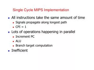
Multiple cycle implementation
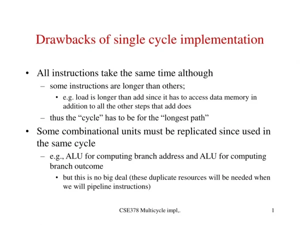
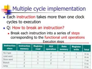
Multiple cycle implementation. Each instruction takes more than one clock cycles to execution Q: How to break an instruction? Break each instruction into a series of steps corresponding to the functional unit operations. Execution steps. buffers. Abstract of multicycle datapath.

Multiple cycle implementation
E N D
Presentation Transcript
Multiple cycle implementation • Each instruction takes more than one clock cycles to execution • Q: How to break an instruction? • Break each instruction into a series of steps corresponding to the functional unit operations Execution steps
buffers Abstract of multicycle datapath • 3 main func. units: memory, register, ALU
Change from single-cycle to multi-cycle • Usage of functional units • A functional unit can be used more than once per instruction on different clock cycles • Ex. Instruction memory, data memory -> one memory • Ex. ALU, adder -> single ALU • Temporary registers as buffers after operational units • IR, MDR, A, B, ALUout • 除了IR外,不需 write control signal。IR需保存指令至指令結束 同一功能單元可在同一指令的不同時脈中使用 Ref: next page 不同時脈間的執行結果需存在暫存器中
Change from single-cycle to multi-cycle (cont.) • How to select input to shared functional units? • Use Multiplexor • Ex. ALU input • Input1: register file 1 PC • Input2: register file 2 constant 4 sign-extended offset shifted offset Ref: prev. page
Do not need write control Multicycle datapath for MIPS: add control lines
6 bits 26 bits Possible sources for PC 1. Normal: PC+4 2. Branch: calculate branch target from ALU 3. Jump: J-format Jump target address 26 bits PC 00 31… 28
PC control lines PC source Multicycle datapath for MIPS: add PC control lines
0 1
Break instruction execution into clock cycles Clock cycle length 時脈長度: longest of these 3 operations
Maximally 5 steps to execute • 3 to 5 steps to execute an instruction Instruction fetch Data/register read Instruction execution Memory/register read/write Register write IR=Memory[PC]; PC=PC+4 A=Reg[IR[25-21]]; B=Reg[IR[20-16]]; calc. branch address Memory reference R-type inst. Branch Jump
3. ALUout=A+sign(IR[15-0]); ALUSrcA=1,ALUSrcB=10 4. MDR = Memory[ALUout]; IorD=1, MemRead=1, 5. Reg[IR[20-16]]=MDR; RegWrite=1, RegDst=0, MemtoReg=1 Example: Memory reference (load) lw $t1, offset($t2)
Add $t1, $t2, $t3 Quiz: R-type Instruction fetch Data/register read Instruction execution Memory/register read/write Register write
Control for multi-cycle datapath • Recall: we build truth table in single cycle datapath • Multicycle: different control signals at the series of steps in a instruction • 2 methods • Finite state machine • microprogramming 指令中每個 cycle 都需要不同的控制訊號
state state transition function Finite state machine Idea for multi-cycle control • 在 datapath 中每個階段都需要不同的控制訊號 Instruction fetch Data/register read Instruction execution Memory/register read/write Register write Memory reference R-type inst. Branch Jump Control Signal 1 Control Signal 2
Preview of FSM for control Inst. Fetch+ Reg. read execution Memory Read/write Write back register
ROM, PLA State transition state Implement FSM
Control for multicycle datapath Microprogramming
Motivation • If there are over 100 instructions, the graphical representation of FSM is impossible… 大指令集,要畫出 FSM 的狀態轉移圖很難
Instructions for datapah Ideas from programming instructions Control signal datapath microinstruction: define the datapath control signals in a given state microprogramming: design the control as a program composed of micro-instructions
Microinstruction format • 依所控制的功能單元分欄位 ALU register memory PC
微指令對應到的控制訊號 下一個指令: 循序執行或有 branch Implement microprogramming