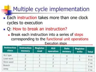
Multiple Cycle Processor Summary
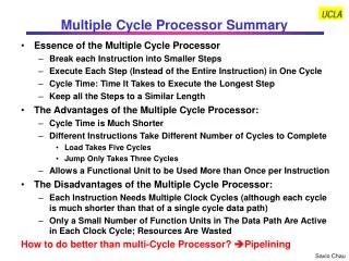
Multiple Cycle Processor Summary. Essence of the Multiple Cycle Processor Break each Instruction into Smaller Steps Execute Each Step (Instead of the Entire Instruction) in One Cycle Cycle Time: Time It Takes to Execute the Longest Step Keep all the Steps to a Similar Length

Multiple Cycle Processor Summary
E N D
Presentation Transcript
Multiple Cycle Processor Summary • Essence of the Multiple Cycle Processor • Break each Instruction into Smaller Steps • Execute Each Step (Instead of the Entire Instruction) in One Cycle • Cycle Time: Time It Takes to Execute the Longest Step • Keep all the Steps to a Similar Length • The Advantages of the Multiple Cycle Processor: • Cycle Time is Much Shorter • Different Instructions Take Different Number of Cycles to Complete • Load Takes Five Cycles • Jump Only Takes Three Cycles • Allows a Functional Unit to be Used More than Once per Instruction • The Disadvantages of the Multiple Cycle Processor: • Each Instruction Needs Multiple Clock Cycles (although each cycle is much shorter than that of a single cycle data path) • Only a Small Number of Function Units in The Data Path Are Active in Each Clock Cycle; Resources Are Wasted How to do better than multi-Cycle Processor? Pipelining
Key Ideas Behind Pipelining • Example: Made- to- Order Hamburger Assembly Line: • Assembly Line Stages: (1) Take the order, (2) Prepare the bun and sauce, (3) Prepare the meat and place it on the bun, (4) Layer the vegetables, (5) Package the product • One Person for Each Stage • Pass the Hamburger and Order to the Next person as Soon as One Finishes His Part • Assume Each Stage Takes 3 minutes to Complete • Each Individual Order Still Takes 15 minutes to Complete • But with 5 People, All Orders can be Completed Much Faster • Each Instruction has Multiple Stages • The Functional Units in Each Stage are Independent • Each Functional Unit Is Used Only Once in Each Instruction • The Next Instruction can Start as Soon as an Instruction Finishes Its Instruction Fetch Stage • Each Instruction Still Takes The Same Number of Cycles to Complete • The Throughput, However, is Much Higher
Example: The 5 Stages of Load Without Pipelining: Latency = 5 cycles Throughput = 0.2 instructions/cycle (or cycles/instruction = 5) • IFetch: Instruction Fetch • Fetch the Instruction from the Instruction Memory • Reg/ Dec: Registers (Operand) Fetch and Instruction Decode • Exec: Calculate the Memory Address • Mem: Read the Data from the Data Memory • Wr: Write the Data Back to the Register File
IFetch IFetch IFetch Reg/Dec Reg/Dec Reg/Dec Exec Exec Exec Mem Mem Mem WrBack WrBack WrBack Pipelining The Load Instructions • The Five Independent Functional Units In the Pipeline Datapath are: • Instruction Memory for the IFetch Stage • Register File’s Read Ports (busA and busB) for the Reg/ Dec Stage • ALU for the Exec Stage • Data Memory for the Mem Stage • Register File’s Write Port (busW) for the Wr Stage • One Instruction Enters the Pipeline Every Cycle • One Instruction Comes Out of the Pipeline (Complete) Every Cycle • The “Effective” Cycles per Instruction (CPI) is 1 Cycle 1 Cycle 2 Cycle 3 Cycle 4 Cycle 5 Cycle 6 Cycle 7 Clk 1st lw 2nd lw 3rd lw Question: How can we stack the execution of the instructions? Answer: By inserting “Pipeline Registers”
Performance of An Ideal Pipeline • Latency of Pipeline = Latency of a Single Task • Potential Throughput Improvement = Number of Pipeline Stages Under The Ideal Situations That All Instructions Are Independent and No Branch Instructions • Pipeline Rate is Limited by the Slowest Pipeline Stage Cycle 1 Cycle 2 Cycle 3 Cycle 4 Cycle 5 Cycle 6 Cycle 7 Clk IFetch Reg/Dec Exec Mem WrBack 1st lw IFetch Reg/Dec Exec Mem WrBack 2nd lw IFetch Reg/Dec Exec Mem WrBack 3rd lw
Mixing Different Types of Instructions in a Pipeline Load and R-Type Instructions in Multi Cycle Data Path • Load Instruction • IFetch: Instruction Fetch • Reg/ Dec: Registers (Operand) Fetch and Instruction Decode • Exec: Calculate the Memory Address • Mem: Read the Data from the Data Memory • Wr: Write the Data Back to the Register File • R-Type Instruction • IFetch: Instruction Fetch • Reg/ Dec: Registers (Operand) Fetch and Instruction Decode • Exec: ALU Operates on the Two Register Operands • Wr: Write the Data Back to the Register File
Cycle 1 Cycle 2 Cycle 3 Cycle 4 Cycle 5 Cycle 6 Cycle 7 Cycle 8 Clk IFetch Reg/Dec Exec WrBack R Type IFetch Reg/Dec Exec WrBack Oops! We Get a Problem! R Type IFetch Reg/Dec Exec Mem WrBack lw IFetch Reg/Dec Exec WrBack R Type IFetch Reg/Dec Exec WrBack R Type Pipelining an R- type and a Load Instruction • Both the Load and R-Type Instructions Try to Write to the Register File at the Same Time!
Solution: Delay R- Type’s Write by One Cycle Cycle 1 Cycle 2 Cycle 3 Cycle 4 Cycle 5 Cycle 6 Cycle 7 Cycle 8 • This actually can easily be done. Just make sure all instructions pass through the same number of pipeline stages and set the control signals of the unused stages to NOP (i.e., all control signals set to 0) • Now R- Type Instructions Also Use Reg File’s Write Port at Stage 5 • Mem Stage is a NOP Stage: Nothing is Being Done Clk IFetch Reg/Dec Exec Mem/Nop WrBack R Type IFetch Reg/Dec Exec Mem/Nop WrBack R Type IFetch Reg/Dec Exec Mem WrBack lw IFetch Reg/Dec Exec Mem/Nop WrBack R Type IFetch Reg/Dec Exec Mem/Nop WrBack R Type IFetch Reg/Dec Exec Mem/Nop WrBack R Type
A Pipelined Datapath Notice how the pipeline registers are labeled
Details of the Execution Unit lw instruction
The Instruction Fetch Stage Instruct Fetch Unit lw instruction
The Decode / Register Fetch Stage Instruct Fetch Unit The 2nd (R-type) instruction can start instruction fetch lw instruction
Load’s Address Calculation Stage Instruct Fetch Unit The 3rd (R-type) instruction can start instruction fetch The 2nd (R-type) instruction can start decode/reg fetch lw instruction
Load’s Memory Access Stage Instruct Fetch Unit The 4th (R-type) instruction can start instruction fetch The 3rd (R-type) instruction can start decode/reg fetch The 2nd (R-type) instruction can start Execution lw instruction
Load’s Write Back Stage Instruct Fetch Unit The 5th (R-type) instruction can start instruction fetch The 4th (R-type) instruction can start decode/reg fetch lw instruction The 3rd (R-type) instruction can start Execution The 2nd (R-type) instruction is no-op in memory access
How About Control Signals? Key Observations • Control signal at stage N is the function of only the instruction at that stage • When an instruction is in stage N, only the control signals in that stage are relevant to the instruction Instruct Fetch Unit
Pipelining the Control Signals • The above observations imply the control signals can be pipelined: • The Main Control Generates the Control Signals During Reg/ Dec • Control Signals for Exec (ExtOp, ALUSrc, ...) are Used 1 Cycle Later • Control Signals for Mem (MemWr Branch) are Used 2 Cycles Later • Control Signals for Wr (MemtoReg RegWr) are Used 3 Cycles Later
Putting It All Together ExtOp ALUSrc ALUOp RegDst MemWr Branch MemtoReg RegWr Control Signals Control Signals Control Signals Main Control PC+4 Instruction Fetch Unit
Mixing More Types of Instructions in a Pipeline Store and Beq Instructions in Multi Cycle Data Path • Store Instruction • IFetch: Instruction Fetch from Instruction Memory • Reg/ Dec: Registers (Operand) Fetch and Instruction Decode • Exec: Calculate the Memory Address • Mem: Write the Data into the Data Memory • Wr: Not applicable. All control signals set to 0 • Beq Instruction • IFetch: Instruction Fetch from the Instruction Memory • Reg/ Dec: Registers (Operand) Fetch and Instruction Decode • Exec: ALU compares the Two Register Operands • Adder Calculates the Branch Target Address • Mem: If the Registers we Compared in the Exec Stage are the Same • Write the Branch Target Address into the PC • Wr: Not applicable. All control signals set to 0
Pipelining Example: End of Cycle 4 12: Beq’s ifetch 8: Store’s Dec 4: R-types’ Exec 0: Load’s Mem Instruct Fetch Unit
Pipelining Example: End of Cycle 5 16: R-type’s ifetch 12: Beq’s Dec 8: Store’s Exec 4: R-types’ Mem 0: Load’s Wr Instruct Fetch Unit
Pipelining Example: End of Cycle 6 20: R-type’s ifetch 16: R-type’s Dec 12: Beq’s Exec 8: Store’s Mem 4: R-types’ Wr Instruct Fetch Unit
Pipelining Example: End of Cycle 7 12: Beq’s Mem (select PC addr) 8: Store’s Wr (No op) 24: R-type’s ifetch 20: R-type’s Dec 16: R-type’s Exec Instruct Fetch Unit
Example of Detailed Pipeline Operations --/IF IF/ID ID/EX EX/MEM MEM/WB PCsrc 0 M wb wb wb u 1 Control x <31:26> m m ex ALUop Add Add Branch MemtoR MemRd RegWrite MemWr x4 4 <10:0> ALU Zero Control rs PC ALUsrc Rd Reg1 Addr rt A RdReg2 MEM/WB EX/MEM IF/ID ID/EX mdo Instruction Addr Registers ALUout zero Memory ALU Rd Data B 0 Wr Reg Data M out 0 u Wr Data 1 Memory M x u Clk PC 1 00 lw $2, 0($3) 2 04 add $4, $0, $5 3 08 sw $6, 4($3) 4 12 addi $7, $2, 100 5 16 add $8, $2, $5 6 20 add $9, $2, $4 7 24 sub $10, $4, $7 8 28 add $11, $7, $8 B 1 x Wr Data <15:0> <31:0> Ext RegDst rt rt 0 ALUout M rd rd u rd rd 1 x See MIPS Example in Class
Comparing Single Cycle, Multiple Cycle, & Pipeline • Disadvantages of the Single Cycle Processor • Long cycle time • Cycle time is too long for all instructions except the Load • Multiple Clock Cycle Processor • Divide the instructions into smaller steps • Execute each step (instead of the entire instruction) in one cycle • Pipeline Processor • Natural enhancement of the multiple clock cycle processor • Each functional unit can only be used once per instruction • If an instruction is going to use a functional unit: • It must use it at the same stage as all other instructions • Pipeline Control: • Each stage’s control signal depends ONLY on the instruction that is currently in that stage
Write with Real Memory: A Real World Problem • At the Beginning of the Wr Stage, We Have a Problem If: • RegAdr’s (Rd or Rt) Clk- to- Q > RegWr’s Clk- to- Q • Similarly, at the Beginning of the Mem Stage, We Have a Problem If: • WrAdr’s Clk- to- Q > MemWr’s Clk- to- Q • Write signal happens too early and invalid data will be written. We Have a Race Condition Between Address and Write Enable!
Synchronize Register File & Synchronize Memory • Solution: And the Write Enable Signal with the Clock • This is the ONLY place where gating the clock is used • MUST consult circuit expert to ensure no timing violation: • Example: Clock High Time > Write Access Delay