Download
1 / 49
520 likes | 660 Vues
Gain a comprehensive understanding of radar operation, components, and types including pulse transmission and continuous wave systems. Learn about frequency modulation, antennas, and influencing factors on radar performance.

E N D
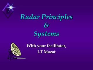
Radar Principles & Systems With your facilitator, LT Mazat
I. Learning ObjectivesA. The student will comprehend the basic operation of a simple pulse radar system. B. The student will know the following terms: pulse width, pulse repetition frequency, carrier frequency, peak power, average power, and duty cycle. C. The student will know the block diagram of a simple pulse radar system and will comprehend the major components of that system.
D. The student will comprehend the basic operation of a simple continuous wave radar system. E. The student will comprehend the concept of doppler frequency shift. F. The student will know the block diagram of a simple continuous wave radar system and will comprehend the major components of that system, including amplifiers, power amplifiers, oscillators, and waveguides.
G. The student will comprehend the use of filters in a continuous wave radar system. H. The student will know the fundamental means of imparting information to radio waves and will comprehend the uses, advantages, and disadvantages of the various means. I. The student will comprehend the function and characteristics of radar/radio antennas and beam formation.
J. The student will comprehend the factors that affect radar performance. K. The student will comprehend frequency modulated CW as a means of range determination. L. The student will comprehend the basic principles of operation of pulse doppler radar and MTI systems.
Two Basic Radar Types • Pulse Transmission • Continuous Wave
Range vs. Power/PW/PRF • Minimum Range: If still transmitting when return received RETURN NOT SEEN. • Max Range: As min Rh max Rh PW PRF
2. Pulse repetition frequency (PRF) • a. Pulses per second • b. Relation to pulse repetition time (PRT) • c. Effects of varying PRF • (1) Maximum range • (2) Accuracy • 3. Peak power • a. Maximum signal power of any pulse • b. Affects maximum range of radar
4. Average power • a. Total power transmitted per unit of time • b. Relationship of average power to PW and PRT • 5. Duty cycle • a. Ratio PW (time transmitting) to PRT (time of entire cycle, time transmitting plus rest time) • b. Also equal to ratio of average power to peak power • C. Discuss the determination of range with a pulse radar.
Determining Range With Pulse Radar c = 3 x 10⁸ m/sec t is time to receive return divide by 2 because pulse traveled to object and back
Pulse Transmission • Pulse Width (PW) • Length or duration of a given pulse • Pulse Repetition Time (PRT=1/PRF) • PRT is time from beginning of one pulse to the beginning of the next • PRF is frequency at which consecutive pulses are transmitted. • PW can determine the radar’s minimum detection range; PW can determine the radar’s maximum detection range. • PRF can determine the radar’s maximum detection range.
D. Describe the components of a pulse radar system. • 1. Synchronizer • 2. Transmitter • 3. Antenna • 4. Duplexer • 5. Receiver • 6. Display unit • 7. Power supply
Pulse Radar Block Diagram Transmitter Synchronizer RF ATR Duplexer (Switching Unit) Antenna Power Supply Echo TR Receiver Video Display Antenna Bearing or Elevation
Continuous Wave Radar • Employs continual RADAR transmission • Separate transmit and receive antennas • Relies on the “DOPPLER SHIFT”
Doppler Frequency Shifts Motion Away: Echo Frequency Decreases Motion Towards: Echo Frequency Increases
Continuous Wave Radar Components Antenna Transmitter CW RF Oscillator OUT IN Discriminator Mixer AMP Antenna Indicator
Pulse Echo Single Antenna Gives Range, usually Alt. as well Susceptible To Jamming Physical Range Determined By PW and PRF. Continuous Wave Requires 2 Antennae Range or Alt. Info High SNR More Difficult to Jam But Easily Deceived Amp can be tuned to look for expected frequencies Pulse Vs. Continuous Wave
RADAR Wave Modulation • Amplitude Modulation • Vary the amplitude of the carrier sine wave • Frequency Modulation • Vary the frequency of the carrier sine wave • Pulse-Amplitude Modulation • Vary the amplitude of the pulses • Pulse-Frequency Modulation • Vary the Frequency at which the pulses occur
Freq. mod. Amplitude modulation Modulation Pulse-amplitude modulation Pulse frequency modulation
Antennae • Two Basic Purposes: • Radiates RF Energy • Provides Beam Forming and Focus • Must Be 1/2 of the Wave Length for the maximum wave length employed • Wide Beam pattern for Search, Narrow for Track
Concentrating Radar Energy Through Beam Formation • Linear Arrays • Uses the Principle of wave summation (constructive interference) in a special direction and wave cancellation (destructive interference) in other directions. • Made up of two or more simple half-wave antennas. • Quasi-optical • Uses reflectors and “lenses” to shape the beam.
Reflector Shape • Paraboloid - Conical Scan used for fire control - can be CW or Pulse • Orange Peel Paraboliod - Usually CW and primarily for fire control • Parabolic Cylinder - Wide search beam - generally larger and used for long-range search applications - Pulse
Wave Shaping -Quasi-Optical Systems Lenses Reflectors
Wave Guides • Used as a medium for high energy shielding. • Uses A Magnetic Field to keep the energy centered in the wave guide. • Filled with an inert gas to prevent arcing due to high voltages within the waveguide.
Questions? Please read Ch 9.
Signal Reception Receiver Bandwidth Pulse Shape Power Relation Beam Width Pulse Repetition Frequency Antenna Gain Radar Cross Section of Target Signal-to-noise ratio Receiver Sensitivity Pulse Compression Scan Rate Mechanical Electronic Carrier Frequency Antenna aperture Factors That Affect Radar Performance
Radar Receiver Performance Factors • Signal Reception • Signal-to-Noise Ratio • Receiver Bandwidth • Receiver Sensitivity
• Only a minute portion of the RF is reflected off the target. • Only a fraction of that returns to the antenna. • The weaker the signal that the receiver can process, the greater the effective range . Signal Reception
Signal-to-Noise Ratio • Measured in dB!!!!! • Ability to recognize target in random noise. • Noise is always present. • At some range, noise is greater that target’s return. • Noise sets the absolute lower limit of the unit’s sensitivity. • Threshold level used to remove excess noise.
Receiver Bandwidth • Is the frequency range the receiver can process. • Receiver must process many frequencies • Pulse are generated by summation of sine waves of various frequencies. • Frequency shifts occur from Doppler Effects. • Reducing the bandwidth • Increases the signal-to-noise ratio(good) • Distorts the transmitted pulse(bad)
Receiver Sensitivity • Smallest return signal that is discernible against the noise background. • Milliwatts range. • An important factor in determining the unit’s maximum range.
Pulse Effects on Radar Performance • Pulse Shape • Pulse Width • Pulse Compression • Pulse Power
Pulse Shape • Determines range accuracy and minimum and maximum range. • Ideally we want a pulse with vertical leading and trailing edges. • Very clear signal – easily discerned when listening for the echo.
Pulse Width • Determines the range resolution. • Determines the minimum detection range. • Can also determine the maximum range of radar. • The narrower the pulse, the better the range resolution.
Pulse Compression • Increases frequency of the wave within the pulse. • Allows for good range resolution while packing enough power to provide a large maximum range.
Pulse Power • The “Ummph” to get the signal out a long way. • High peak power is desirable to achieve maximum ranges. • Low power means smaller and more compact radar units and less power required to operate.
Other Factors Affecting Performance • Scan Rate and Beam Width • Narrow beam require slower antenna rotation rate. • Pulse Repetition Frequency • Determines radars maximum range(tactical factor). • Carrier Frequency • Determines antenna size, beam directivity and target size. • Radar Cross Section (What the radar can see(reflect)) • Function of target size, shape, material, angle and carrier frequency.
Summary of Factors and Compromises Factor Trade-off Required Desired Why Pulse Shape Sharp a rise as possible Better range accuracy Require infinite bandwidth, more complex Tall as possible More power /longer range Requires larger equipment/more power Pulse Width Short as possible Closer minimum range Reduces maximum range More accurate range Pulse Repetition Freq. Short Better range accuracy Reduces maximum range Better angular resolution Better detection probability Pulse Compression Uses technique Greater range More complex circuitry Shorter minimum range Power More Greater maximum range Requires larger equipment & power Beam Width Narrow Greater angular accuracy Slow antenna rate, Detection time Carrier Frequency High Greater target resolution Reduces maximum range Detects smaller targets Smaller equipment Receiver Sensitivity High Maximizes detection range More complex equipment Receiver Bandwidth Narrow Better signal-to-noise ratio Distorts pulse shape Summary of Factors and Compromises
Specific Types of Radar • Frequency Modulated CW Radar • Use for radar altimeters and missile guidance. • Pulse Doppler • Carrier wave frequency within pulse is compared with a reference signal to detect moving targets. • Moving Target Indicator (MTI) System • Signals compared with previous return to enhance moving targets. (search radars) • Frequency Agile Systems • Difficult to jam.
Specific Types of Radar • SAR / ISAR • Phased Array - Aegis • Essentially 360° Coverage • Phase shift and frequency shift allow the planar array to “steer” the beam. • Also allows for high / low power output depending on requirements.
Questions? Transmission Wasted Echo Echo