Download

1 / 57
570 likes | 870 Vues
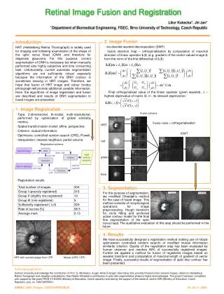
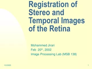
Registration of Retinal Images. Yogesh Babu Bathina Advisor : Jayanthi Sivaswamy Centre for Visual Information Technology (CVIT) IIIT-Hyderabad, India. Summary. Introduction to Image registration Retinal imaging background Motivation Application Challenges

E N D
Registration of Retinal Images Yogesh Babu Bathina Advisor : Jayanthi Sivaswamy Centre for Visual Information Technology (CVIT) IIIT-Hyderabad, India
Summary • Introduction to Image registration • Retinal imaging background • Motivation • Application • Challenges • Retinal image registration paradigm • Relevant literature • Proposed framework • Vessel enhancement • Landmark detection • Radon based descriptor for feature matching • Transformation estimation at various stages • Experimental setup and results • Conclusion and future work • Feedback, reviews and questions
Image Registration Image Registration is the task of spatially align two or more images of the same scene/object acquired from different sources, view points and time. T : f (x) → g(x’) ⇔ T (f (x)) = g(x′) f (x) and g(x′) be two images of the same scene/object, where x=(x1,x2) and x’=(x1’,x2’) for 2D images. T is the transformation function that maps one image into the coordinates of other. f (x) g(x’) T (f (x)) = g(x′) T T Note : Image registration is not image fusion
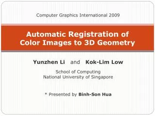
Applications of Registration • Remote Sensing: Multi-spectral classification, Environmental monitoring, Change detection, Image mosaicing, Weather forecasting, Integrating information into geographic information systems (GIS) • Computer Vision: Tracking, Stereo-vision, Object recognition, Target localization, Super-resolution images ,etc. • Medicine: Diagnosis, Surgery planning and Intervention, Mosaicing, Tracking, fusion, Super-resolution etc A generic registration algorithm for all applications? Geometric and radiometric deformations, noise, image characteristics, required accuracy and stability are to be considered [1]. [1] Barbara Zitova, Jan Flusser, “Image registration methods: a survey”Image and Vision Computing, 2003
Broad Classification of Registration Algorithms Lisa Gottesfeld Brown, “A Survey of Image Registration Techniques”ACM Computing Surveys, 1992
Classification of Registration Algorithms: Area based methods Area based registration
Classification of Registration Algorithms: Feature based methods Feature based registration
Classification of Registration Algorithms: Global Vs Local mapping Global Mapping (rigid) Local Mapping(non-rigid)
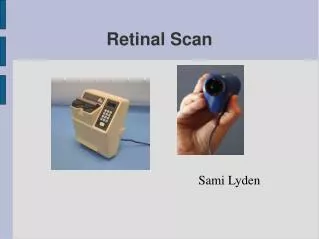
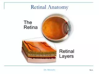
Background: Retinal Imaging Cross sectional view of the eye Anatomy of the eye Retinal Imaging setup
Background: Retinal Images • Obtained under natural light • Non-invasive • Over health of retina • Color image • Single image Optic disk Macula Vessels Color Fundus Image(CFI) FluorosceneFundus Angiogram (FFA) • Obtained under infrared light • Invasive • Reveals blood flow dynamics • Grayscale image • Time sequence Red Free Image(RFI) images similar to CFI
Motivation • Retina is part of the central nervous system. • Excellent indicator of systemic diseases like diabetics[3] • 366 million 2013 and 552 million 2030 affected by diabetics • 75% of diabetic adults develop diabetic retinopathy. • 10% severe visual impairment. • Other systemic diseases include Hypertension, Atherosclerosis, Sickle cell disease, Multiple sclerosis • Recent research reveals association of retinal vascular signs to cerebrovascular, cardiovascular and metabolic outcomes [3 ] http://www.hki.org/preventing-blindness
Retinal Image Registration and its Applications • Disease tracking • Image mosaic • Surgery planning • Localization of disorders • Super-resolution Monomodal Registration Monomodal retinal image registration -Checkerboard view Multimodal Registration • Improve anatomical range • for visual inspection • Surgery planning and • intervention • Image Fusion • CAD system evaluation Multimodal retinal image registration
Challenges in retinal Image registration • Retina is a curved surface, induces radial distortion when imaged on to a plane • Images may be acquired from uncalibrated cameras. • Varying resolution • Complementary information in multimodal Images. • ill timed acquisition of FFA images. • Variable field of view and overlap • Poor contrast of images, especially FFA. • Green channel noise, non uniform illumination. • Pathology affected retina
Registration paradigm in computer vision and medical imaging • Feature based registration • Global mapping(rigid) • Monomodal/Natural images • Posed as regression problem Computer Vision Medical imaging • Area based registration • Local mapping (non-rigid) • Medical images/ Multimodal • Posed as an optimization problem Our approach to retinal image registration Given the advantages of feature based registration, develop a registration scheme for both monomodal and multimodal retinal image registration.
Relevant literature • Charles V. Stewart, Chia ling Tsai, and BadrinathRoysam. The dual-bootstrap iterative closest point algorithm with application to retinal image registration.IEEE Trans. Med. Img, 2007. GDBICP • J. Chen, J. Tian, N. Lee, J. Zheng, R. Smith, and A. Laine. A partial intensity invariant feature descriptor for multimodal retinal image registration.IEEE Trans Biomed Eng, 2010 PIIFD
Overview of Proposed Registration Algorithm Yogesh Babu & JayanthiSivaswamy, “Robust registration of poor quality Retinal Images”To be submitted
Vessel Enhancement • Single representation • Handle degradations. • Boost tubular structures • Minimize the presence of pathologies Goal of vessel enhancement Vessel enhanced subimages of CFI and FFA
Vessel Enhancement Method Given an image (x) , where x={x,y}, the Scale space representation is given by Hessian matrix The eigen values (λ1,λ2) and eigen vectors (v1,v2) principle curvatures and their orientations. The vesselness measure for various scales is given by Topographic view of sub image Lxx A.Frangi, W. Niessen, Koen L. Vincken, Max A. Viergever, “Multiscale vessel enhancement filtering”MICCAI, 1998
Vessel Enhancement Method The final vessel enhanced R is given by The eigen vectors corresponding to R (x) is computed as Subimage Vessel enhanced image Principle minima directions Landmark detection method Tony Lindeberg, “Scale-Space Theory in Computer Vision” , KTH, 1994
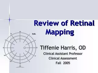
Landmark Detection • Vessels are the best representatives • Junctions/cross-over points are not enough Proposed new landmark detection characteristics: They are widely spread (2)They have maximum presence on vasculature Vessel junctions & cross over points as landmarks[5] [5]K.Ram, Y.Babu, J. Sivaswamy, “Curvature orientation histograms for the detection and matching of vascular landmarks in retinal Images”SPIE- Medical Imaging 2009
Landmark detection: Candidate Selection stage CS-Ito give a rough structural vessel map t1 is the threshold selected as 10% of the max( s) FFA sub-image with lesions Rough structural map PBg
Landmark detection candidate selection stage CS-II, detects high curvature points using the determinant of Hessian blob detector. PDh candidates through determinant of hessian operator
Landmark detection candidate selection stage PDhPBg the output of candidate selection stage on CFI image
Landmark detection :Curvature Dispersion Measure Curvature Dispersion measure: Principle minima orientation map Final set of landmarks are obtained after non-maximal suppression. [5]K.Ram, Y.Babu, J. Sivaswamy, “Curvature orientation histograms for the detection and matching of vascular landmarks in retinal Images”SPIE- Medical Imaging 2009
Landmark detection Result Landmark detection in CFI image
Radon based Descriptor For each landmark point: (1) A patch of wxw is extracted from the vessel enhanced image. w=(w1,w2…wn) n=4 (2) Compute the dominant direction in the patch. (3) Starting from dominant orientation compute radon transform at uniform angular intervals. (4) Normalise each projection and append profile to form feature vector. Size:720 Radon Transform YogeshBabu, N.V. KartheekandJayanthiSivaswamy,” Robustmatchingofmulti-modalretinalimagesusingradontransformbasedlocaldescriptor” ACM-International Health Informatics, Nov- 2010
Overview of Proposed Registration Algorithm P0 Q0 Dq Dp
Bilateral matching Bilateral matching: Euclidean Normalized similarity measure (in (0,1]). Euclidean normalised similarity measure. http://www .lans.ece.utexas.edu/ strehl/diss/node53.html
Overview of Proposed Registration Algorithm P0 Q0 C0 Dq Dp
Transformation models for retinal image registration • The appropriate transformation model for registering retinal images is a quadratic model to account for the curved surface of the retina[4] • In low overlap cases, with limited pairs of landmarks, bilinear transformation is used [4] Can A., Stewart C.V., RoysamB., TanenbaumH.L,” A feature-based, robust, hierarchical algorithm for registering pairs of images of the curved human retina” PAMI, 2002
Initial transformation estimation and outlier rejection using modified MSAC • Assume affine transformation for outlier rejection. • M-estimator Sample and Consensus (MSAC) framework is used. • Two steps in modified MSAC : • Hypothesis is based on selection of top few correspondences to generate the Minimal Sample Set. Use Angle-Angle property of similar triangles to discard false matches. • Verification is based on cost function instead of rank unlike RANSAC algorithm. • Break down criteria is 50%. • Convergence criteria is same as RANSAC Refinement & localization of correspondences using Normalized cross correlation for sub-pixel accuracy https://en.wikipedia.org/wiki/Similarity_(geometry)#Similar_triangles M. Zuliani. Ransac toolbox for matlab, Nov. 2008,”RANSAC for dummies”.
Initial transformation estimation and outlier rejection using modified MSAC result Correspondence set C1 after outlier rejection between CFI and FFA
Overview of Proposed Registration Algorithm C2 C1 P0 Q0 C0 Dq Dp
Model selection and transformation estimation • The spatial distribution of correspondences pairs is used to determine the transformation models. • This is determined by computing the entropy of the spatial distribution. • Final transformation function is estimated using the standard M-estimators. • Since no closed form solution exists, it is implemented using iteratively reweighted least squares method[4]. No contribution here • Moving image is resampled into the coordinates of the fixed image using bicubic interpolation. Quadratic Bilinear Affine [4] Can A., Stewart C.V., RoysamB., TanenbaumH.L,” A feature-based, robust, hierarchical algorithm for registering pairs of images of the curved human retina” PAMI, 2002
Experimental setup • 3 datasets • Dataset 1: 126 multimodal pairs • Dataset II :20 monomodal pairs • Dataset III : 18 multimodal and monomodal pairs (challenge) • Resolution between 256x256 to 1204x1200 • Angular resolution between 30° - 50° • Comparison using PIIFD(2011) and GDBICP (gold standard). • Time taken 70-80 Secs. • Evaluation criteria: • Mean centerline measurement error • Overall registered images in dataset I,II and III • Rotational Invariance test • Scale Invariance test • Overlap Test
Results • Mean Centerline Measurement Error(M-CME) • Overall registered images in dataset I,II and III M-CME Dataset III 18 images • Charles V. Stewart, Chia ling Tsai, and BadrinathRoysam. The dual-bootstrap iterative closest point algorithm with application to retinal image registration.IEEE Trans. Med. Img, 2007. • J. Chen, J. Tian, N. Lee, J. Zheng, R. Smith, and A. Laine. A partial intensity invariant feature descriptor for multimodal retinal image registration.IEEE Trans Biomed Eng, 2010 Dataset I 126 images Dataset II 20 images
Results • Rotational Invariance test M-CME ±1.8 • Scale Invariance test Invariant up a factor1.8 • Overlap Test Robust up to 25% overlap
Results Results from dataset I
Conclusion and future work • A novel registration algorithm to register both multimodal and monomodal retinal Images. • Contributions: • Vessel enhancement - Minor • Landmark Detection -Major • Radon based Descriptor –Major • Initial transformation estimation – Major(speedup only) • Transformation model selection –Minor • Out performs existing methods for poor quality images and performs on par with GDBICP for healthy retinal images. • Drawbacks: • Contrast reversal. • Algorithm is randomized • Feature descriptor length 720 • Speed
Future work • Integral Image representation for Faster processing. • Faster background estimation instead of median for landmark detection. • Like PCA-SIFT, reduce dimensionality of the feature vector. • Extend to other modalities. • Super resolution and information fusion Super resolution Information fusion
Extension to other modalities Partial fingerprint matching Partial fingerprint matching
Reviewers Feedback & Questions • Add conclusion and future work as a separate chapter -Done • In chapter 3: Is a bin size of 15° acceptable for curvature orientation histogram for landmark correspondence?. • No, We developed a new method to over come these limitations • In chapter 4. what is the computation al cost of using 31x31 medians when most of your images are 3000x3000 in size. How much time does this median filter take. • Size of images between 256x256 to 1204x1200, Time:6 secs • Also, throughout chapter 4, there are a lot of magic numbers. Is it possible to give some intuition about their values and how sensitive the performace of your approach is to small variations in the values. • Sensitive parameters: No.of scales, Radon descriptor bins and no.of projections, Curvature dispersion measure(Non maximal suppression). • Others have little impact: Ex: Median filter may vary between 21-41.
Reviewers Feedback & Questions • Am I correct in thinking that PIIFD performs better than your method for overlaps of less than 30% between images. What are the general overlap percentages for fundus images? • 40% is the minimum overlap. • PIIFD handles less then 30% (as per publication), we saw drop in accuracy, as per our standard they do not qualify. • The dataset which they used for evaluation is proprietary. On our dataset, poor registration is seen.