Status of laser system
170 likes | 306 Vues
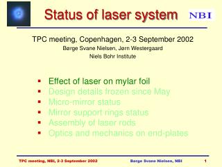
Status of laser system. Micro-mirror production status New support of micro-mirrors in rods Micro-mirror z positions New beam transport to muon arm side NBI lab tests: 1 mm beam profiles preliminary high voltage tests Absolute versus relative calibrations.

Status of laser system
E N D
Presentation Transcript
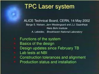
Status of laser system • Micro-mirror production status • New support of micro-mirrors in rods • Micro-mirror z positions • New beam transport to muon arm side • NBI lab tests: • 1 mm beam profiles • preliminary high voltage tests • Absolute versus relative calibrations TPC meeting, CERN, 29-30 April 2002 B.S.Nielsen, J. Westergaard Niels Bohr Institute Børge Svane Nielsen, NBI
TPC Laser principle Børge Svane Nielsen, NBI
Laser tracks in TPC Børge Svane Nielsen, NBI
Micro-mirror production A.Ridiger, Moscow: all fibres cut, polished, coated and tested 43 of 60 mirror bundles produced angle measurements about to start micro-mirror bundle brass cup protection cap Børge Svane Nielsen, NBI
Laser rod with mirrors drawing shown in December 2001 New: Alu ring design changed & mirror support integrated with rings Børge Svane Nielsen, NBI
Mirror support rings New: mirror support integrated with Alu rings: Prototype produced at NBI Børge Svane Nielsen, NBI
Rod gluing mirror support ring: normal gas rod Alu ring: normal gas rod macrolon piece: Børge Svane Nielsen, NBI
Micro-mirror z positions (1) Principle of choosing z positions: • 4 micro-mirrors per rod, at about (0, 1/3, 2/3, 1) length • vary z positions slightly between odd/even rod • Normal gas rod consists of sections: 180+10210+180 mm • with alu rings inbetween. • In laser rod: • cut first and last section in two and insert laser ring • replace 2 normal rings with laser rings in odd rods • cut 2 middle sections and insert laser rings in even rods Børge Svane Nielsen, NBI
Micro-mirror z positions (2) 12 normal gas rods: 12 laser rods (full TPC): Suggestion: All mirror support rings glued to short rods and 6 long rods at NBI. Full rods glued at CERN. Børge Svane Nielsen, NBI
New muon arm side beam transport limited space between TPC and space frame move beam transport 10º from vertical plane adds 2 mirrors on sharf side + modifies beam transport on muon side beam transport as foreseen alternatives possible new layout new placement special prism special prism hope to attach 50 mm pipe on outside of TPC permanently Børge Svane Nielsen, NBI
Laser lab at NBI rod with micro-mirrors CCD camera power supply 1064 nm laser amplifier expandingtelescope quadrupler 266 nm doubler 532 nm Børge Svane Nielsen, NBI
Reflected 1 mm beam z=31cm z=200cm FWHM=.93mm FWHM=.95mm Børge Svane Nielsen, NBI
Reflected 1 mm beams (2) z=13 cm 16 cm 19 cm FWHM=1.00mm 1.00mm 1.01mm 47 cm 31 cm 23 cm 1.10mm 0.93mm 1.17mm 100cm 150cm 200cm 0.93mm 0.79mm 0.95mm Børge Svane Nielsen, NBI
Preliminary HV tests 10200 M total L=2.10 m 70-80 kV 40 A @ 80 kV in air 200 M laser off/on: no change in current (1 A) Børge Svane Nielsen, NBI
Laser system objectives(P. Glässel) • Electronics testing • Sector alignment • Drift velocity monitoring • Pressure, temperature • Temperature gradients (stratification?) • ExB effects, space charge • Two possible approaches: • Relative measurements, rely only on time stability of laser ray position • Absolute measurements, requires knowledge of absolute position of laser ray. More ambitious Børge Svane Nielsen, NBI
Stability of laser and beams System with micro-mirrors laser ray positions determined by the mirror positions and angles, not by the main laser beam. We are trying to assure the best possible mechanical stability in the construction and to make position measurements during installation. This should make the system better than most previous ones. But: we cannot assure laser system position stability better than the tolerances and movements of the support structure (rods and cylinders). Mechanical stability of the TPC is good enough for precise (100 m) relative measurements once the TPC is installed. During installation, the TPC will undergo stresses due to handling (turning on end) and change of loads (ROCs, cables etc). ’Absolute’ positions must refer to something that it stable or measured relative to something else well-known: ROCs, central electrode... ? Børge Svane Nielsen, NBI
How obtain ’absolute’ positions? • What is known precisely and ’absolutely’? (100-200 m ?) • central electrode z position • pad plane z and gating wire z and x/y position • special effort: measure beams near inner cylinder for beams close to end-plate with TPC in horizontal position before installation of IROCs • Well measured relative to each other (100 m, 0.05 mrad): • internal angles in micro-mirror bundles • micro-mirror bundles in support rings • bundle support rings in uninstalled rods • Less well measured or prone to move (500 m, 0.2 mrad): • rod positions relative to ROCs, central electrode and ALICE x,y,z • Probably needs ’internal alignment’ and iterations: • precise position and angles of beams far from end-plates • everything that may move due to twists of cylinders, rods etc. Børge Svane Nielsen, NBI