CHAPTER THREE: IRRIGATION METHODS AND DESIGNS
CHAPTER THREE: IRRIGATION METHODS AND DESIGNS. 3.1 IRRIGATION METHODS a) Surface Irrigation: Just flooding water. About 90% of the irrigated areas in the world are by this method.

CHAPTER THREE: IRRIGATION METHODS AND DESIGNS
E N D
Presentation Transcript
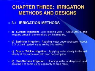
CHAPTER THREE: IRRIGATION METHODS AND DESIGNS • 3.1 IRRIGATION METHODS • a) Surface Irrigation: Just flooding water. About 90% of the irrigated areas in the world are by this method. • b) Sprinkler Irrigation: Applying water under pressure. About 5 % of the irrigated areas are by this method. • c) Drip or Trickle Irrigation: Applying water slowly to the soil ideally at the same rate with crop consumption. • d) Sub-Surface Irrigation: Flooding water underground and allowing it to come up by capillarity to crop roots.
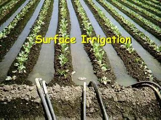
3.2 SURFACE IRRIGATION • Water is applied to the field in either the controlled or uncontrolled manner. • Controlled: Water is applied from the head ditch and guided by corrugations, furrows, borders, or ridges. • Uncontrolled: Wild flooding. • Surface irrigation is entirely practised where water is abundant. The low initial cost of development is later offset by high labour cost of applying water. There are deep percolation, runoff and drainage problems
3.2.1 Furrow Irrigation • In furrow irrigation, only a part of the land surface (the furrow) is wetted thus minimizing evaporation loss. • Furrow irrigation is adapted for row crops like corn, banana, tobacco, and cabbage. It is also good for grains. • Irrigation can be by corrugation using small irrigation streams. • Furrow irrigation is adapted for irrigating on various slopes except on steep ones because of erosion and bank overflow.
Furrow Irrigation Contd. • There are different ways of applying water to the furrow. • As shown in Fig. 3.1, siphons are used to divert water from the head ditch to the furrows. • There can also be direct gravity flow whereby water is delivered from the head ditch to the furrows by cutting the ridge or levee separating the head ditch and the furrows (see diagram from Gumb's book). • Gated pipes can also be used. Large portable pipe(up to 450 mm) with gate openings spaced to deliver water to the furrows are used. • Water is pumped from the water source in closed conduits. • The openings of the gated pipe can be regulated to control the discharge rate into the furrows.
3.2.1.1 Design Parameters of Furrow Irrigation • The Major Design Considerations in Surface Irrigation Include: • Storing the Readily Available Moisture in the Root Zone, if Possible; • Obtaining As Uniform Water Application As Possible; • Minimizing Soil Erosion by Applying Non-erosive Streams; • Minimizing Runoff at the End of the Furrow by Using a Re-use System or a Cut -Back Stream; • Minimizing Labour Requirements by Having Good Land Preparation, • Good Design and Experienced Labour and • Facilitating Use of Machinery for Land Preparation, Cultivation, Furrowing, Harvesting Etc.
Furrow Irrigation Contd. • The Specific Design Parameters of Furrow Irrigation Are Aimed at Achieving the Above Objectives and Include: • a) Shape and Spacing of Furrows: Heights of ridges vary between 15 cm and 40 cm and the distance between the ridges should be based on the optimum crop spacing modified, if necessary to obtain adequate lateral wetting, and to accommodate the track of mechanical equipment. • The range of spacing commonly used is from 0.3 to 1.8 m with 1.0 m as the average.
Design Parameters of Furrow Irrigation Contd. • b) Selection of the Advance or Initial Furrow Stream: In permeable soils, the maximum non-erosive flow within the furrow capacity can be used so as to enable wetting of the end of the furrow to begin as soon as possible. • The maximum non-erosive flow (Qm) is given by: Qm = c/S where c is a constant = 0.6 when Qm is in l/s and S is slope in %. • Example 1: For a soil slope of 0.1 %, the Qm is 0.6/0.1 = 6 l/s.
Design Parameters of Furrow Irrigation Contd. • The actual stream size should be determined by field tests. • It is desirable that this initial stream size reaches the end of the furrow in T/4 time where T is the total time required to apply the required irrigation depth. • c) Cut-back Stream: This is the stream size to which the initial stream is reduced sometime after it has reached the lower end of the field. • This is to reduce soil erosion. • One or two cutbacks can be carried out and removing some siphons or reducing the size at the head of the furrow achieves this.
Design Parameters of Furrow Irrigation Contd. • d) Field Slope: To reduce costs of land grading, longitudinal and cross slopes should be adapted to the natural topography. • Small cross slopes can be tolerated. • To reduce erosion problems during rainfall, furrows (which channel the runoff) should have a limited slope (see Table 3.1).
Table 3.1 : Maximum Slopes for Various Soil Types Soil Type Maximum slopes* Sand 0.25 Sandy loam 0.40 Fine sandy loam 0.50 Clay 2.50 Loam 6.25 Source: Withers & Vipond (1974) • *A minimum slope of about 0.05 % is required to ensure surface drainage.
Design Parameters of Furrow Irrigation Contd. • e) Furrow Length: Very long lengths lead to a lot of deep percolation involving over-irrigation at the upper end of the furrow and under-irrigation at the lower end. • Typical values are given in Table 3.2, but actual furrow lengths should be got from field tests.
Design Parameters of Furrow Irrigation Contd. • e) Field Widths: Widths are flexible but should not be of a size to enclose variable soil types. • The widths should depend on land grading permissible.
3.2.1.2 Evaluation of a Furrow Irrigation System • The objective is to determine fairly accurately how the system is used and to suggest possible amendments or changes. • Equipment: Engineers Level and Staff, • 30 m Tape, • Marker Stakes, • Siphons of Various Sizes, • Two Small Measuring Flumes, • Watch with Second Hand and Spade.
Evaluation of a Furrow Irrigation System Contd. • Procedure • a) Select several (say 3 or more) uniform test furrows which should be typical of those in the area. • b) Measure the average furrow spacing and note the shape, condition etc. • c) Set the marker stakes at 30 m intervals down the furrows. • d) Take levels at each stake and determine the average slope. • e) Set the flumes say 30 m apart at the head of the middle furrow. • f) Pass constant flow streams down the furrows, using wide range of flows. The largest flow should just cause erosion and overtopping, the smallest might just reach the end of the furrow. The median stream should have a discharge of about Q = 3/4 S (l/s) where S is the % slope.
Evaluation of a Furrow Irrigation System Contd. • g) Record the time when flow starts and passes each marker in each flow(advance data). • h) Record the flow at each flume periodically until the flows become practically constant. This may take several hours on fine textured soils(Infiltration data). • i) Check for evidence of erosion or overtopping. • j) Move the flumes and measure the streams at the heads only of the other furrows. • Results: To be presented in a format shown: • ............................................................................................................ • Watch Opportunity time(mins) • Station A Station B Losses • Time A B C Depth Flow Depth Flow Diff Infil. • (mm) ( L/s) (mm) (L/s) (L/s) (mm/h) • ..............................................................................................................
3.2.2. Border Irrigation System • In a border irrigation, controlled surface flooding is practised whereby the field is divided up into strips by parallel ridges or dykes and each strip is irrigated separately by introducing water upstream and it progressively covers the entire strip. • Border irrigation is suited for crops that can withstand flooding for a short time e.g. wheat. • It can be used for all crops provided that the system is designated to provide the needed water control for irrigation of crops. • It is suited to soils between extremely high and very low infiltration rates.
Border Irrigation Contd. • In border irrigation, water is applied slowly. • The root zone is applied water gradually down the field. • At a time, the application flow is cut-off to reduce water loses. • Ideally, there is no runoff and deep percolation. • The problem is that the time to cut off the inflow is difficult to determine.
3.2.2.2 Design Parameters of Border Irrigation System • a) Strip width: Cross slopes must be eliminated by leveling. • Since there are no furrows to restrict lateral movement, any cross slope will make water move down one side leading to poor application efficiency and possibly erosion. • The stream size available should also be considered in choosing a strip width. • The size should be enough to allow complete lateral spreading throughout the length of the strip. • The width of the strip for a given water supply is a function of the length (Table 3.5). • The strip width should be at least bigger than the size of vehicle tract for construction where applicable.
Design Parameters of Border Irrigation System Contd. • b) Strip Slope: Longitudinal slopes should be almost same as for the furrow irrigation. • c) Construction of Levees: Levees should be big enough to withstand erosion, and of sufficient height to contain the irrigation stream. • d) Selection of the Advance Stream: The maximum advance stream used should be non-erosive and therefore depends on the protection afforded by the crop cover. Clay soils are less susceptible to erosion but suffer surface panning at high water velocities. Table 3.4 gives the maximum flows recommendable for bare soils. • e) The Length of the Strip: Typical lengths and widths for various flows are given in Table 3.5. The ideal lengths can be obtained by field tests.
3.2.2.3 Evaluation of a Border Strip • The aim is to vary various parameters with the aim of obtaining a good irrigation profile. • Steps • a) Measure the infiltration rate of soils and get the cumulative infiltration curve. Measurement can be by double ring infiltrometer. Depth of Water, D (mm) D = KTn Time, T (mins) Fig 3.5: Cumulative Infiltration Curve
Evaluation of Border Strip Contd. • b) Mark some points on the border strip and check the advance of water. Also check recession. For steep slopes, recession of water can be seen unlike in gentle slopes where it may be difficult to see. In border irrigation, recession is very important because unlike furrows, there is no place water can seep into after water is turned off.
Evaluation of the Border System Contd. • About two-thirds down the border, the flow is turned off and recession starts. • The difference between the advance and recession curves gives the opportunity time or total time when water is in contact with the soil. • For various distances, obtain the opportunity times from the advance/recession curves and from the cumulative infiltration curve, obtain the depths of water. • With the depth and distance data, plot the irrigation profile depth shown below.
Evaluation of the Border System Contd. • The depth of irrigation obtained is compared with the SMD (ideal irrigation depth). • There is deep percolation and runoff at the end of the field. • The variables can then be changed to give different shapes of graphs to see the one to reduce runoff and deep percolation. In this particular case above, the inflow can be stopped sooner. The recession curve then changes. • The profile now obtained creates deficiency at the ends of the borders (see graph: dotted lies above). • A good profile of irrigation can be obtained by varying the flow, which leads to a change in the recession curve, and by choosing a reasonable contact time each time using the infiltration curve.
3.2.3 Basin Irrigation System • 3.2.3.1 Description: In basin irrigation, water is flooded in wider areas. It is ideal for irrigating rice. • The area is normally flat. • In basin irrigation, a very high stream size is introduced into the basin so that rapid movement of water is obtained. • Water does not infiltrate a lot initially. • At the end, a bond is put and water can pond the field. • The opportunity time difference between the upward and the downward ends are reduced.
Basin Irrigation Diagram I rrigation time.
3.2.3.2 Size of Basins • The size of basin is related to stream size and soil type(See Table 3.6 below). • Table 3.6: Suggested basin areas for different soil types and rates of water flow • Flow rate Soil Type • Sand Sandy loam Clay loam Clay • l/s m3 /hr .................Hectares................................ • 30 108 0.02 0.06 0.12 0.20 • 60 216 0.04 0.12 0.24 0.40 • 90 324 0.06 0.18 0.36 0.60 • 120 432 0.08 0.24 0.48 0.80 • 150 540 0.10 0.30 0.60 1.00 • 180 648 0.12 0.36 0.72 1.20 • 210 756 0.14 0.42 0.84 1.40 • 240 864 0.16 0.48 0.96 1.60 • 300 1080 0.20 0.60 1.20 2.00 • ........................................................................................... • Note: The size of basin for clays is 10 times that of sand as the infiltration rate for clay is low leading to higher irrigation time. The size of basin also increases as the flow rate increases. The table is only a guide and practical values from an area should be relied upon. There is the need for field evaluation.
3.2.3.3 Evaluation of Basin System • a) Calculate the soil moisture deficiency and irrigation depth. • b) Get the cumulative infiltration using either single or double ring infiltrometer. I = c Tn Infiltered Depth (mm) Time (mins)
Evaluation of a Basin System Contd. • c) Get the advance curves using sticks to monitor rate of water movement. Plot a time versus distance graph (advance curve). Also plot recession curve or assume it to be straight • It is ensured that water reaches the end of the basin at T/4 time and stays T time before it disappears. At any point on the advance and recession curves, get the contact or opportunity time and relate it to the depth-time graph above to know the amount of water that has infiltrated at any distance.
Evaluation of Basin Irrigation Concluded. • Check the deficiency and decide whether improvements are necessary or not. The T/4 time can be increased or flow rate changed. The recession curve may not be a straight line but a curve due to some low points in the basin.
3.3 SPRINKLER IRRIGATION • 3.3.1 Introduction: The sprinkler system is ideal in areas where water is scarce. • A Sprinkler system conveys water through pipes and applies it with a minimum amount of losses. • Water is applied in form of sprays sometimes simulating natural rainfall. • The difference is that this rainfall can be controlled in duration and intensity. • If well planned, designed and operated, it can be used in sloping land to reduce erosion where other systems are not possible.
3.3.2 Types of Conventional Sprinkler Systems • a) Fully portable system: The laterals, mains, sub-mains and the pumping plant are all portable. • The system is designed to be moved from one field to another or other pumping sites that are in the same field. • b) Semi-portable system: Water source and pumping plant are fixed in locations. • Other components can be moved. • The system cannot be moved from field to field or from farm to farm except when more than one fixed pumping plant is used.
Types of Conventional Sprinkler Systems Contd. • c) Fully permanent system: Permanent laterals, mains, sub-mains as well as fixed pumping plant. • Sometimes laterals and mainlines may be buried. • The sprinkler may be permanently located or moved along the lateral. • It can be used on permanent irrigation fields and for relatively high value crops e.g. Orchards and vineyards. • Labour savings throughout the life of the system may later offset high installation cost.
3.3.3 Mobile Sprinkler Types • a) Raingun: A mobile machine with a big sprinkler. • The speed of the machine determines the application rate. The sprinkler has a powerful jet system. • b) Lateral Move: A mobile long boom with many sprinklers attached to them. • As the machine moves, it collects water from a canal into the sprinklers connected to the long boom.
Centre Pivot • c) Centre Pivot: The source of water is stationary e.g. a bore hole. The boom with many sprinklers rotates about the water source.