Download
1 / 30
310 likes | 472 Vues
This chapter delves into fundamental principles of optics, specifically focusing on the speed of light in a vacuum, reflection, and refraction. It highlights Michelson's groundbreaking 1878 Rotating Mirror Experiment, which achieved unprecedented accuracy in measuring the speed of light. The text explains wavefronts, rays, Snell's law, total internal reflection, and dispersion, with illustrations such as Huygens' principle. Additionally, it discusses polarization, including linear and circular polarization, and Brewster's law. This comprehensive overview serves as a foundation for understanding light behavior in different media.

E N D
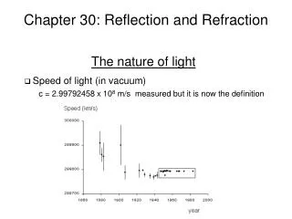
Chapter 30: Reflection and Refraction • Speed of light (in vacuum) c = 2.99792458 x 10⁸ m/s measured but it is now the definition The nature of light
Michelson’s 1878 Rotating Mirror Experiment • German American physicist A.A. Michelson realized, on putting together Foucault’s apparatus, that he could redesign it for much greater accuracy. • Instead of Foucault's 60 feet to the far mirror, Michelson used 2,000 feet.. • Using this method, Michelson was able to calculate c = 299,792 km/s • 20 times more accurate than Foucault • Accepted as the most accurate measurement of c for the next 40 years. Picture credit
Waves, wavefronts, and rays • Wavefront: The locus of all adjacent points at which the phase of • vibration of a physical quantity associated with the wave is the same. rays The nature of light source wavefronts spherical wave plane wave
Reflection and refraction • When a light wave strikes a smooth interface of two transparent • media (such as air, glass, water etc.), the wave is in general partly • reflected and partly refracted (transmitted). incident rays reflected rays Reflection and refraction a a b b refracted rays
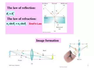
Reflection • The incident, reflected, and refracted rays, and the normal to the • surface all lie in the same plane. reflected rays incident rays • The angle of reflection is equal to • the angle of incidence for all • wavelengths and for any pair of • material. Reflection and refraction a b refracted rays
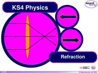
Refraction • The index of refraction of an optical material (refractive index), denoted • by n, is the ratio of the speed of light c in vacuum to the speed v in the • material. wavelength in vacuum. Freq. stays the same. reflected rays incident rays • The ratio of the sines of the angles • and , where both angles are • measured from the normal to the • surface, is equal to the inverse ratio • of the two indices of refraction: Reflection and refraction a b Snell’s law refracted rays
Total internal reflection Total internal reflection when Since When this happens, is 90o and is called critical angle. Furthermore when , all the light is reflected (total internal reflection).
Optical fibers Total internal reflection
Dispersion • The index of refraction of a • material depends on wavelength • as shown on the right. This is • called dispersion. It is also true that, • although the speed of light in vacuum • does not depends on wavelength, • in a material wave speed depends • on wavelength. Dispersion
Examples Diversion
Huygens’ principle Every point of a wave front may be considered the source of secondary wavelets that spread out in all directions with a speed equal to the speed of propagation of the wave. Plane waves Huygens’ principle
Huygens’ principle (cont’d) • Huygens’ principle for plane wave • At t = 0, the wave front is indicated by the plane AA’ • The points are representative sources for the wavelets • After the wavelets have moved a distance cDt, a new plane BB’ can be drawn tangent to the wavefronts
Huygens’ principle for spherical wave Huygens’ principle (cont’d)
Huygens’ principle (cont’d) • Huygens’ principle for spherical wave (cont’d) • The inner arc represents part of the spherical wave • The points are representative points where wavelets are propagated • The new wavefront is tangent at each point to the wavelet
Huygens’ principle (cont’d) • Huygens’ principle for law of reflection • The Law of Reflection can be derived from Huygen’s Principle • AA’ is a wavefront of incident light • The reflected wave front is CD
Huygens’ principle (cont’d) • Huygens’ principle for law of reflection (cont’d) • Triangle ADC is congruent to triangle AA’C • Angles q1 = q1’ • This is the law of reflection
Huygens’ principle (cont’d) • Huygens’ principle for law of refraction • In time Dt, ray 1 moves from A to B and ray 2 moves from A’ to C • From triangles AA’C and ACB, all the ratios in the law of refraction can be found: n1 sin q1 = n2 sin q2
EM wave y In the text: E(x,t)=jEmaxcos(kx-wt) B(x,t)=kBmaxcos(kx-wt) ^ x ^ z Polarization • Polarization (defined by the direction of ) Linear polarization Circular polarization
Polarization (defined by the direction of ) Circular polarization Polarization (cont’d)
Polarizing filters Polarization (cont’d)
Polarization by reflection Polarization (cont’d) plane of incidence When the angle of incident coincides with the polarizing angle or Brewster’s angle, the reflected light is 100% polarized. Brewsters’s law of the polarizing angle
Example: depth of a swimming pool Pool depth s = 2m person looks straight down. the depth is judged by the apparent size of some object of length L at the bottom of the pool (tiles etc.) q2 q1 L
q2 q1 L for small angles: tan ->sin
Example: Flat refracting surface • The image formed by a flat refracting surface is on the same side of the surface as the object • The image is virtual • The image forms between the object and the surface • The rays bend away from the normal since n1 > n2 L q1 q2 q2
Example: 1 = 30 Prism example • Light is refracted twice – once entering and once leaving. • Since n decreases for increasing , a spectrum emerges... Analysis: (60 glass prism in air) sin 1 = n2 sin 2 n2 sin 3 = sin 4 n1 = 1 60 n2 = 1.5 a+b+60o = 180o 3 = 90 - = 90 - 2 3 = 60 - 2
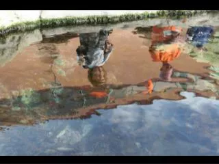
Atmospheric Refraction and Sunsets • Light rays from the sun are bent as they pass into the atmosphere • It is a gradual bend because the light passes through layers of the atmosphere • Each layer has a slightly different index of refraction • The Sun is seen to be above the horizon even after it has fallen below it
Mirages • A mirage can be observed when the air above the ground is warmer than the air at higher elevations • The rays in path B are directed toward the ground and then bent by refraction • The observer sees both an upright and an inverted image
Problem 1 The prism shown in the figure has a refractive index of 1.66, and the angles A are 25.00 . Two light rays m and n are parallel as they enter the prism. What is the angle between them they emerge? A m A n Solution Exercises Therefore the angle below the horizon is and thus the angle between the two emerging beams is
Problem 2 Light is incident in air at an angle on the upper surface of a transparent plate, the surfaces of the plate being plane and parallel to each other. (a) Prove that (b) Show that this is true for any number of different parallel plates. (c) Prove that the lateral displacement d of the emergent beam is given by the relation: where t is the thickness of the plate. (d) A ray of light is incident at an angle of 66.00 on one surface of a glass plate 2.40 cm thick with an index of refraction 1.80. The medium on either side of the plate is air. Find the lateral Displacement between the incident and emergent rays. n Q t n’ P n d Exercises
Problem 2 Solution • For light in air incident on a parallel-faced • plate, Snell’s law yields: • (b) Adding more plates just adds extra steps • in the middle of the above equation that • always cancel out. The requirement of • parallel faces ensures that the angle • and the chain of equations can continue. • (c) The lateral displacement of the beam can be calculated using geometry: • (d) n Q t n’ P n L d Exercises