SWIM Integrated Plasma Simulator for Fusion Physics
230 likes | 328 Vues
SWIM integrates RF wave interactions with magnetohydrodynamics for fusion plasma physics. The IPS design is based on wrapping existing codes to allow coupling of various fusion physics models for complete simulation.

SWIM Integrated Plasma Simulator for Fusion Physics
E N D
Presentation Transcript
The SWIM Integrated Plasma Simulator Wael R. Elwasif, Lee A. Berry, Donald B. Batchelor, and David E. Bernholdt (bernholdtde@ornl.gov) Oak Ridge National Laboratory for the Center for Simulation of RF Wave Interactions with Magnetohydrodynamics http://www.cswim.org Work supported in part by the Scientific Discovery through Advanced Computing (SciDAC) program, Offices of Advanced Scientific Computing Research and Fusion Energy Sciences, U. S. Dept. of Energy. Oak Ridge National Laboratory is managed by UT-Battelle, LLC for the US Dept. of Energy under contract DE-AC-05-00OR22725.
Center for Simulation of RF Wave Interaction with Magnetohydrodynamics (SWIM) • Focus on integrated modeling of RF and MHD • One of three integrated simulation projects currently funded by DOE SciDAC program • Participating Institutions • Columbia University, CompX, General Atomics, Indiana University, Massachusetts Institute of Technology, Oak Ridge National Laboratory, Princeton Plasma Physics Laboratory , University of Wisconsin • Collaborators: Lawrence Berkeley National Laboratory, Lehigh University, New York University • Leadership Team • Don Batchelor, ORNL (Lead PI) • Steve Jardin, PPPL • Randy Bramley, Indiana (CS Lead) • David Keyes, Columbia (Applied Math Lead)
SWIM brings together two mature sub-disciplines of fusion plasma physics, each with a demonstrated code base using the most advanced computers High power wave-plasma interactions – CSWPI Extended MHD – CEMM • MHD equilibrium • Macroscopic fluid instability • Current and magnetic field evolution • Plasma heating • Externally driven current or plasma flow • Non-Maxwellian particle distributions Fluid equations, extended to include non-ideal and kinetic effects (10-5 sec < tMHD < 10-1 sec) Plasma wave equation (tRF < 10-7 sec), coupled to slow evolution of plasma velocity distribution (tFP > 10-2 sec) Why couple these particular two disciplines? • Macroscopic instabilities can limit plasma performance • RF waves can mitigate and control instabilities
MHD << HEATING Te0 time MHD ~ HEATING Te0 time SWIM Science Goals Two sets of physics goals distinguished by the time scale of unstable MHD motion Fast MHD phenomena – separation of time scales • Response of plasma to RF much slower than fast MHD motion • RF drives slow plasma evolution, sets initial conditions for fast MHD event • Example: sawtooth crash Slow MHD phenomena – no separation of time scales • RF affects dynamics of MHD events MHD modifications affect RF drive plasma evolution • Deals with multi-scale issue of parallel kinetic closure including RF – a new, cutting edge field of research • Example: Neoclassical Tearing Mode We are approaching these regimes in two campaigns of software development and physics analysis and validation
MHD << HEATING MHD ~ HEATING Integrated Plasma Simulator (IPS) Te0 Simulation of plasma evolution requires complete model • Heating and current drive sources • Particle sources • Transport • Magnetic field evolution time Te0 time Integrated Plasma Simulator will allow coupling of virtually any fusion fusion code, not just RF and MHD, and should provide the framework for a full fusion simulation
SWIM Software Goals & Requirements • CS “constrained” by science requirements, but pushing the envelope as far as we can • Develop an Integrated Plasma Simulator (IPS) supporting… • SWIM’s science needs (near term) • Design study for future full integrated simulations (long term) • Explore interoperability and interchangeability of components in common infrastructure • Looking towards a flexible “toolkit” for integrated modeling • Useful for V&V • Maximize (re)use of existing code • Minimize code changes for non-scientific reasons • Capable of running on high-end systems from the start
IPS Design Approach • Framework/component architecture • Components initially existing codes wrapped up • Framework provides basic utility services • “Driver” component orchestrates simulation • “Plasma State” component is official data manager • Emphasize interfaces • Components providing the same functionality should do so through the same interface • Project intentionally includes at least two distinct codes for most classes of functionality • Some groups included (and funded) specifically for this reason! • Start simple, increase sophistication as science needs dictate • File-based communication in-memory data exchange • Whole codes wrapped with Python scripts finer-grain native-language components • Project-specific Python framework Common Component Architecture compliant framework
Important Disclaimer! • The IPS is definitely work in progress • This talk presents a snapshot of the current system • If you’re looking at this after 10 May 2007, we’re sure to have changed things! • Contact us if the latest details matter to you!
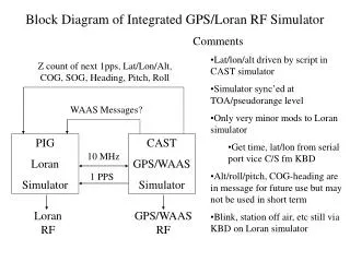
IPS Framework Initializes plasma state as needed for chosen simulation Provides basic support for file management, job control, portal interface, etc. Setup init rf.ic AORSA Driver XPlasma plasma_state Orchestrates and sequences calculations, makes decisions about control flow in response to component results All data exchange between components goes through XPlasma TSC epa fokker_planck CQL3D Components implement (one or more) specific interfaces. A given interface may have multiple implementations. Schematic of an IPS Application
IPS Framework Features • Provides environment in which components are instantiated and executed • Manages association between interfaces and components implementing them • Provides basic services to components • Configuration (input) management • Easily extensible to add’l components w/o outside changes • Hoping to leverage “machine configuration file” from elsewhere • File management abstraction • Manages working directories • Notion of temporary and permanent files, stored separately • Job management (parallel execution) • Interface with web portal • Without changes to underlying components • Currently all part of a single services interface • Probably should be separated into multiple services
The Basic Interface • Observation • Most coarse-grain (application-level) components in a time-stepped simulation can be expressed with just a few basic operations • Init(ialize) • Prepare to run component for a series of time steps • Step • Do whatever computation is appropriate to the current time step • Finalize • Clean up at end of run • All data exchanged via Plasma State
Sketch of Basic IPS Driver Read in simulation configuration Setup initial plasma state Foreach component c (in appropriate order) Call c.init For t = ti to tf Foreach component c (in appropriate order) Call c.step(t) Commit this time step to Plasma state Stage output files Foreach component c (in appropriate order) Call c.finalize
IPS Framework Setup init AORSA rf.ic XPlasma plasma_state TSC epa CQL3D fokker_planck Schematic of an IPS Application Driver
Prepare_inputhelper executable Python wrapper provides entire external interface Local AORSAinput files AORSA rf.ic rf.ic.aorsaPython wrapper AORSAexecutable plasma_state XPlasma Local AORSAoutput files Fortran helpers map global XPlasma data objects to/from AORSA-specific files Process_outputhelper executable Schematic Component Internals Driver IPS design/specifications say nothing about internal implementation of components.
Responding to Unplanned Events… • Life is usually a little more complicated: how do components communicate back to the driver? • Example scenarios • Control actions (modifications to coil currents, heating or current drive power, fueling, etc.) may be dynamically scheduled, and don’t necessarily occur on timestep boundaries • Equilibrium and profile advance component detects a sawtooth event • All components return status information • Report problems with execution (components must never abort!) • Report exceptional events encountered in simulation • Information rich object, not just an integer (exception in computer science terminology) • Driver responds to component exceptions as appropriate • Only the driver has the “big picture” of the simulation, not individual components! • Might rollback current step and recompute from t to texcept • Might keep some results and recompute others
… Requires a Richer Component Interface • Init/step/finalize interface is insufficient to respond to many exceptional conditions • Extend basic interface with additional actions besides step, for example… • RF.solve, RF.rescale_power • NB.advance, NB.change_power, NB.sawtooth • EPA.advance, EPA.restart • Interfaces are no longer generic across all components • This is not a problem – only components providing the same functionality need to have the same interface • Open question: to what extent can completely different implementations of a given functionality share a common interface? • General question of component approach, not specific to fusion
Plasma State (1) • “Official data store of the IPS” • All data exchanged between components goes through PS • Components are welcome to produce other files • Built on PPPL’s XPlasma2 library • Distributed by NTCC, used in TRANSP • netCDF for backend storage (caveats!) • Formally a library at present, not a component • Fortran module supplies direct access to PS variables (pros and cons) • Requires recompilation of all clients when changes are made • Provides interpolation, etc. capabilities in addition to storage and retrieval
Plasma State (2) • Supports multiple state instances (very important!) • Current/prior state (ps, psp) • Pre-/post-sawtooth (saw0, saw1) • Start/end of pellet injection (pel0, pel1) • … • Store/update/commit protocol • Commit copies current state to prior state and writes • Update is in-memory • PS data conventions (names, units, etc.) for IPS determined by (benevolent) dictator • Extended as needed • Data stored “as produced” • Reader is responsible for adapting as needed • However, see caveat on next slide
Plasma State (3) • Recommend storing only extensive quantities in PS • Use with conservative interpolation techniques • Not all codes produce extensive quantities, may need to be derived for storage in PS • PS code is automatically generated from simple configuration file defining known data objects • Build system required to orchestrate all dependencies • Some physicists don’t trust interface, insist on knowing how the code works under the covers • In this case, code generation! • One of many sociological issues associated with component approach • We don’t know how to deal with distributions yet • Thinking about it! • It may not be as pretty or elegant as it could be, but it works!
Finer grained, more tightly coupled components Needs beginning to appear in fast MHD campaign Stronger needs in slow MHD campaign Interfaces will become less generic as components become narrower in functionality Finer granularity shorter run times too much overhead for file-based data exchange In-memory data exchange May require rethinking of Plasma State Managing parallelism Some components sequential, others highly parallel Test harness for components Unit testing (playback, etc.) Regression testing Migrate to standard component architecture (CCA) Will facilitate leveraging of outside components (I/O, math, etc.), standard infrastructure Current design is (intentionally) close to CCA Looking Forward
A Glimpse of the Future? An Integrated Fusion Simulation Toolkit? • Computational Facility for Reacting Flow Science: a toolkit to perform simulations of unsteady flames • Solve the Navier-Stokes with detailed chemistry • Various mechanisms up to ~50 species, 300 reactions • Structured adaptive mesh refinement • CFRFS today: • 61 components • 7 external libraries • 9 contributors “Wiring diagram” for a typical CFRFS simulation, utilizing 12 components. CCA tools used: Ccaffeine, and ccafe-gui Languages: C, C++, F77
Summary • SWIM has distinct scientific and software goals • Focus on component architecture and developing interfaces to explore interoperability and interchangeability • Framework, driver, plasma state, and physics components are key elements • Components communicate through plasma state • Conventions defined by benevolent dictator, but can be modified and extended • Start simple • Plan for evolution of all aspects of system