Download
1 / 31
310 likes | 505 Vues
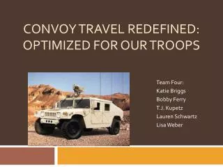
Convoy Travel Redefined: Optimized for our troops. Team Four: Katie Briggs Bobby Ferry T.J. Kupetz Lauren Schwartz Lisa Weber. Mission Statement.

E N D
Convoy Travel Redefined:Optimized for our troops Team Four: Katie Briggs Bobby Ferry T.J. Kupetz Lauren Schwartz Lisa Weber
Mission Statement We have concluded that we must design a device that has the ability to detect and relay information about roadway obstructions to the drivers of vehicles in formation. The design must be able to function in all weather, especially low visibility conditions. It must not be detectable either by light given off or by emitting traceable wavelengths. It must be easily manufactured and the training must be easily relayed to the user. Finally, the technology used in the device must warrant the high cost.
Problem Statement As requested by BAE Systems, Team 4 has designed a sensor system in accordance with the initial problems of convoy travel as laid out by BAE and discovered through further research. These obstacles include, but are not limited to; oncoming traffic, debris in the road, and ditches in the path. Also, our key focus of avoidance will be to detect a crater 1 meter wide and deep with 2 meters in procession direction and to establish a path around this obstacle. However, these obstacles have been acknowledged by taking many other various factors into account such as terrain, velocity of the vehicle, and climate conditions. Through avoidance of obstacles, the terrain was taken into account in which the roads are paved rather poorly being asphalt poured over bare ground. Also, the velocities of the vehicles have been taken into account in which the reaction time of the vehicle when faced with an obstacle is quite acute. Another aspect that was considered is the close proximity of the other vehicles in convoy so that accidents may be avoided. Finally, the climate was taken into account in which the temperatures are exceedingly hot and the missions are frequently faced with sandstorms in which the visibility is very low. It was also very important to design a sensor system with capabilities to be reliable in night conditions, when the troops carry out a large portion of their missions.
Convoy Configuration Small Convoy Large Convoy
Acoustic sensors have been within the industrial market for over 60 years. Although this technology is currently being explored and discovered, there are several current applications being used within the market today. Currently acoustic wave devices are used for calculating torque and tire pressure on cars, they can be found as chemical sensors for medical applications, and there are sensors for vapor, mass, humidity and temperature detectors in a wide range of consumer products on the current market. The function of an acoustic wave sensor is based upon the analysis of returning wave frequencies. When an acoustic wave propagates through or on the surface of a given material, all the changes to the characteristics of the propagation path can affect the velocity and amplitude of the wave. So when the sensor detects a change in pressure or temperature or mass, the returning wave will have an altered amplitude or velocity. Piezoelectricity is the main component of acoustic sensors. The sensors utilize the piezoelectric effect by applying mechanical stress to produce electrical charges. Piezoelectric acoustic wave sensors apply an oscillating electric field to create a mechanical wave, which propagates through the substrate and is then converted back to an electric field for measurement. Acoustic Sensors
Piezoelectric acoustic wave sensors apply an oscillating electric field to create a mechanical wave, which propagates through the substrate and is then converted back to an electric field for measurement. For example in piezoelectric microphones, the acoustic waves detect changes in pressure and sound. When a sound wave is generated, it bends the piezoelectric material which produces a change in voltage, converting the vibrations into an electric signal. When there is a change in the path over which the acoustic wave propagates there will be a change in the sensors output.
Disparity mapping Disparity mapping is a relatively new form of obstacle detection. Disparity cameras work by two cameras being placed at a defined distance from each other. They both focus on at the same angle. As both cameras capture images, a computer can detect objects within the image and by comparing the differences between the two images, detect the depth of the obstructions. Disparity mapping sensors are defined as “passive” because they acquire data in a non-intrusive manner, unlike lasers or radar which emit a beam from the sensor into the environment. This has a distinct advantage in combat situations in which the user must remain covert. However, since they operate on the visible spectrum, low-light situations may form a problem. Currently, Ford is researching a “low-light” camera for use in a potential pre-crash detection system for domestic use. An infrared camera is also being developed, however IR would not suffice for military use due to its easy detection by the enemy. Because disparity mapping needs nothing more than two cameras and a computer, it is a relatively inexpensive sensor.
Long Range Finder Similar in theory to the millimeter wave radar is long range radar. An antenna is mounted on the vehicle and radio waves are transmitted forward. The antennas then record the Doppler shift which shows the velocity of an approaching object. Doppler shift records the change in frequency as explained in the following equation. Wavelength and frequency (initial) is the set radio wave emitted from the sensor. The wavelength increases as the distance between objects increases. This change is the calculation of the Doppler Effect. Using this, we find that the time between the transmission of radio waves and the antenna reception can tell us the distance from the object.
Millimeter Wave Radar Unlike microwave radar, the millimeter wave radar is superior as it is shorter in wavelength. With Doppler frequency capacity the millimeter radar objects can be detected with high-quality precision. Also, capable of forward detection, the millimeter radar is able to detect the presence or the absence of steep slopes directed downward. Also, by the use of backward detection, the millimeter radar is able to detect stationary objects behind the vehicle. Another key feature of the millimeter radar is the storage capability in which vehicles are able to store course data so that the vehicles may avoid stationary obstacles. To obtain the millimeter radar, a vehicle is equipped with four millimeter-wave transmitting and receiving antennas. These antennas are located on the top four corners of the vehicle including the front left, front right, back left, and back right. The lengths of the antennas are approximately 85 millimeters in length. Also, there is an antenna tilted downward approximately 6 degrees. To further describe the millimeter wave, it is an electromagnetic wave with a wave length of 1 to 10 millimeters, which is approximately 300 to 30 GHz. Also, by an FM-CW method, the millimeter wave, the carrier wave, is modulated with a signal wave so that a transmitting wave and a reflected wave will be mixed to receive the beat frequency
Thermal Imaging One of the sensors that could be applied to the current problem would be the thermal imaging sensors. These sensors are not detectable by any other sensors and can be used day or night without blinding the operator with excessive light. Some models have and still are being used and tested in the military in Iraq. Some aspects that make it ideal for the HMMWV drivers are the easy use, long range (up to 1000 feet), and shock and water resistance. This sensor relies on the background radiation that everything gives off (in terms of heat). The hotter the object is, the whiter the object appears, and the colder the object, the blacker it appears. In a cold desert, and living being or automobile would show up very clearly, giving ample time to avoid a conflict. The equipment that is currently in use receives much ‘wear and tear’, so this would be up to the rigor of regular use. This can be set up using a tripod mount or by using it as an eyepiece, and the output can be displayed on an LCD or just left to the eyepiece for personal use or during black-out conditions. The lengths of the antennas are approximately 85 millimeters in length. Also, there is an antenna tilted downward approximately 6 degrees. To further describe the millimeter wave, it is an electromagnetic wave with a wave length of 1 to 10 millimeters, which is approximately 300 to 30 GHz. Also, by an FM-CW method, the millimeter wave, the carrier wave, is modulated with a signal wave so that a transmitting wave and a reflected wave will be mixed to receive the beat frequency
Power can be supplied from an outlet jack or with batteries. It would be able to stand regular use in varying temperatures [(-20°C—60°C) or (-4°F—140°F)] and is very lightweight for use on the go. A prime example of a thermal sensor is the Raytheon X100xp. These are currently being used in military and civilian operations and if given to the convoy drivers, could greatly enhance their viewing and driving ability.
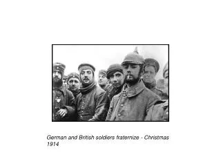
Customer Analysis “All convoys begin with a mission statement. Everybody in the convoy knows they can be shot, blown up, diverted, kidnapped, or otherwise obliterated at any moment along the route. Thus the FEAR factor.” “We know that a flat tire could be deadly, but could also travel a great distance without stopping if we had a blow out. The worst thing was to STOP. There were no safe places to just stop and change a tire, check the oil or things like that. In some cases we had to form a semi-circle with the vehicles and post security while waiting for transport. ”
“I had some friends that were IED’d in their Hummer. The IED was buried in the road and was detonated remotely. It blew through the floor of the vehicle. The gunner (standing in the rear) was killed instantly and landed in the lap of his best friend. The other 3 men were hit with shrapnel and suffered hearing loss, concussions, and minor wounds. The hummer had 4 blown out tires. The other vehicles in the convoy were not hit. The driver continued with the hummer and drove on the rims for 2 miles back to the operating base without delay, all the while my friend Scott lay dead on the lap of his battle buddy. Now you can understand the things we were all most afraid of.”
“Our biggest fear was breaking down in the badlands. All the vehicles had towing winches and cables and we never left on a convoy without confirming that each vehicle was equipped to tow or be towed without delay.” Rich Allinger “The best part of any convoy was when we got back to our base.” Rich Allinger “The vehicle is heavy, strong, and sturdy and has a very wide wheel base. The army versions have no frills and only rarely had air conditioning.” “They are very loud and not at all comfortable, which is fine because that keeps you alert and awake.” Rich Allinger
CONOPS To Prevent This: Goals: -Sustainability -Application -Market -Cost
Analysis After going through both the screening and weighted matrices, the millimeter wave radar appeared to be the most practical product to be installed on the HUMMWV vehicles. The millimeter wave radar is unaffected by fog, rain, snow or other weather conditions; whereas acoustic sensors can be easily altered and diffracted by water, making it unable to operate in rain or snow. A vehicle mounted millimeter wave radar device consists of a hollow structure where a multilayer substrate rests on the inside of the hollow encasing. The millimeter wave MMIC is mounted on the substrate and a cap forming a hollow around the MMIC joins together with an adhesive to maintain a high frequency characteristic. The assembly is them covered in a water resistant resin, allowing the vehicle mount to be water resistant. These components are very low in cost, thus enabling a cheaper product that will have higher productivity.
The millimeter wave radar is superior as it is shorter in wavelength. With Doppler frequency capacity the millimeter radar objects can be detected with high-quality precision. Also, capable of forward detection, the millimeter radar is able to detect the presence or the absence of steep slopes directed downward. Also, by the use of backward detection, the millimeter radar is able to detect stationary objects behind the vehicle. Another key feature of the millimeter radar is the storage capability in which vehicles are able to store course data so that the vehicles may avoid stationary obstacles. The millimeter wave radar is clearly the best choice because not only is it durable in a range of weather conditions, but it is low in cost, reliable and easy to maintain. Millimeter wave radars can pass undetected by the enemy, unlike various lasers and infrared sensors that show up under night vision goggles, and can be maintained and used with ease. The thermal sensor ranked high within the weighted matrix; however it would not provide a clear solution to the problem at hand, which is detecting obstacles and craters in the road. It would provide for a nice modification to the hummer, but it will not serve as our group’s primary focus.
Cost Cost Analysis: Working cost= $30/hr (x2 employees)(x3 installed at a time)(x3hrs) = $540 Test time=$2880 Cost of Materials= $7000 (Thermal Camera) + $18,000 (Millimeter Radar) = $25,000 Basic Cost= $25,000 + $540 + $2880 = $28,420 Total Cost= Basic Cost x 1.3 (profit margin) = $36,946
Through strict analysis of each method and taking various factors into account such as reaction time, sustainability, and reliability; the team has concluded that millimeter wave radar and thermal sensors will be included in our final design. In reference to the millimeter wave radar obstacles such as the crater in the road may be avoided as the radar will detect the obstacle through an antenna and transmit it to video output so that the TC may be notified. As the millimeter wave radar functions with a range of 150m, with reference to the reaction time of the person being 0.75 seconds and the processing time of the radar being 50 milliseconds, the driver will lose 0.8 seconds. Therefore, the driver will have approximately 139 m before the obstacle traveling at a speed of 50 km/s. Once notified, the driver can travel at the same initial speed for approximately 93 m before they will have to make a turn with a radius of 15 m before making the turn at a constant speed. Also, our final design incorporates thermal sensors, which will allow for safety at night. These sensors are not detectable by any other sensors and can be used day or night without blinding the operator with excessive light. The thermal sensor relies on the background radiation that everything gives off (in terms of heat). The hotter the object is, the whiter the object appears, and the colder the object, the blacker it appears. By combining these two sensors, Team 4 has accounted for the obstacles that may obscure the vehicles travel path. The antennas of the millimeter wave radar are located on the top four corners of the vehicle including the front left, front right, back left, and back right to account for any obstacles coming at the vehicle at any angle. The wiring will be located inside the vehicle right below the roof around its perimeter and then be connected to the viewing screen. The millimeter wave radar will be located outside the dashboard in the middle so that it will not obstruct the driver’s view and the thermal sensor will be located on the front of the vehicle. Also, the video screens for the millimeter wave radar and thermal sensor will be located on the passenger’s side on the dashboard so that it will be easily seen by the TC. Through combination of these two sensors, the convoy missions will be carried out safely by being aware of obstacles before they become a difficult problem.
In reference to our diagram the millimeter sensor works through an antenna and radar so that the information can be sent by video output. First, the antenna receives the signal of the perceived obstacle, which, in this case is a crater in the road approximately 1 m wide and deep. Then the information is applied to the receiver by the use of a TR switch. The purpose of this switch is to direct received energy to the receiver and transmitted energy to the antenna. In millimeter wave radar, the TR then acts as a circulator. Then the received RF signal is converted to an IF so that it may be amplified. In the mixer, the transmitted frequency and the local oscillator frequency creates a sum of the two frequencies. Millimeter wave radars use frequencies including 100, 120, 300, and 3000 MHz. These frequencies can then be used to be converted to video output to alert the driver. The vehicles following the point HMMWV must be informed that there is an obstruction in the road. Since the noise within the vehicle has been described as “deafening,” our best solution is to once again put the millimeter radar to use. Due to the Doppler effect, millimeter radar can detect the velocities of objects. Since the formations often change, it is necessary to equip all vehicles with the same devices. Therefore, vehicles following the lead HMMWV can detect it either slowing down or changing its position and remain in formation while taking evasive maneuvers.
Another modification that our group was going to add to the hummers was the capabilities of thermal sensors. These sensors would provide a substantial increase in the viewing capabilities of the HMMWV personnel. The current lighting conditions would not hinder the vision, because unlike the night vision, it does not amplify the light; it displays the radiation signatures that all objects give off – heat being the most visible. This would prevent any blinding due to sudden light variations. Thermal also has a very long visible range – up to 1000 feet – which would allow for an increase in situational awareness. If the convoy were to become enveloped in a sand storm or other weather predicament, the sensor would still allow for the personnel to freely see what is ahead without being affected by the weather. A small sensor could easily be placed into the front grill of the HMMWV, and it is water and shock proof, so it could easily stand up to the elements of frequent use. With this sensor, an eyepiece – very similar to the night vision one the military currently uses – could be used to view the field ahead. If blackout conditions are not needed, then this sensor could be attached to a LCD display. It can run off of the HMMWV battery power, of if needed, can be used with standard AA batteries. There is no light source emanating from the sensor, so it would not be able to be tracked to a source, and safety will not be compromised. In conjunction with the Millimeter Wave Radar, it can indicate where areas of interest will be and the thermal will allow the personnel to view what could be coming up.
Conclusion Our design is the most effective, reliable, and easiest way to assist the driver in detecting obstacles and preventing crashes. The combination of millimeter wave radar and thermal imaging will provide flawless warnings of whatever barrier lies between the HUMVEE and the road to safety. Choosing our design will keep the driver informed, keep the detection minimal, and leave the highways safer. The most important person in the vehicle is the driver. He has control and needs to feel in control. With the two sensors he will feel twice as safe and well-informed. A confident driver results in a successful convoy. If a convoy is detected, enemies attack and the precious lives of our brave soldiers are lost. We can prevent this by eliminating the use of detectable wavelengths. Although both our sensors use wave technology, neither can be detected by outside sources. This ensures the lives of many.