MARIE Instruction Set Architecture
240 likes | 327 Vues
Learn about MARIE ISA with 13 instructions, including LOAD, examine key operations, and how MARIE handles branching and conditional operations. Discover the basics of MARIE register transfer notation.

MARIE Instruction Set Architecture
E N D
Presentation Transcript
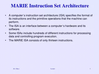
MARIE Instruction Set Architecture • A computer’s instruction set architecture (ISA) specifies the format of its instructions and the primitive operations that the machine can perform. • The ISA is an interface between a computer’s hardware and its software. • Some ISAs include hundreds of different instructions for processing data and controlling program execution. • The MARIE ISA consists of only thirteen instructions. Lecture
MARIE ISA • This is the format of a MARIE instruction: • The fundamental MARIE instructions are: • Specifies the instruction to be executed, therefore 24=16 instructions • Allows for a maximum size of memory of 212 - 1 Lecture
LOAD Instruction • The Load instruction allows data to be moved from memory into the CPU via the MBR and the AC • All data must be first moved into the MBR and then either into the AC or ALU • The Load instruction doesn’t have to name the AC as a final destination, the AC register is implicit in the instruction • This is a bit pattern for a LOAD instruction as it would appear in the IR: • We see that the opcode is 1 and the address from which to load the data is 3. Lecture
Intro to Other Instructions • Allows data to be moved from the CPU back to memory • Typically represented as ASCII. In real-life, has to be converted if used as numeric. For MARIE, assume numeric only • Causes the current program execution to terminate • Move the data value found at address X into the MBR, then add the MBR value to the value in the AC • Move the data value found at address X into the MBR, then subtract the MBR value from the value in the AC • Allows conditional branching (ie. while loops, if statements). When the instruction is executed, the value in the AC is inspected • Allows an unconditional branch. When the instruction is executed, it causes the contents of the Program Counter (PC) to be replaced with the value of X, which is the address of the next instruction to fetch – thus skipping Lecture
SKIPCOND Instruction • As mentioned earlier, when SKIPCOND is executed, the value in the AC is examine • In MARIE’s case, address bits 10 and 11 are examined: • Bits used to specify the condition to be tested • If 00, translates to “bypass the next instruction if the AC is negative” • If 01, translates to “bypass the next instruction if the AC is equal to 0” • If 10, translates to “bypass the next instruction if the AC is greater than 0” • If 11, an error condition occurred • This is a bit pattern for a SKIPCOND instruction as it would appear in the IR: • We see that the opcode is 8 and bits 11 and 10 are 10, meaning that the next instruction will be skipped if the value in the AC is greater than zero. Lecture
Examine Some Instructions • Opcode is binary 1, for LOAD. The address where the value in located in memory is 3. Data found at address 3 is copied into the AC • Opcode is binary 3, for ADD. The address where the value in located in memory is 13. Data found at address 13 is placed in the MBR, then the MBR value is added to the value in the AC, and then the value in the AC is over-written with the sum • Opcode is binary 8, for SKIPCOND. Bits 11 and 10 are 10 indicating bypass the next instruction if the AC is greater than 0. If the AC’s value is less than or equal to zero, this instruction is ignored and the next instruction is executed. Otherwise, the PC is incremented by 1, thus skipping Lecture
MARIE Register Transfer Notation • Instead of using binary values to represent the instruction, instruction names or mnemonics used (pronounced Nee-Monics) • Binary version – called machine instructions • Mnemonics version – called assembly language instructions • An assembler’s job is to convert the assembly instructions into the machine instructions • Recall that architectures are comprised of various components like the ALU, registers, memory decoders and control units • A single machine instruction causes these components to execute tasks • Each machine instruction can consist of multiple component-level operations • Mini-instructions are being executed. These mini-instructions are called microoperations • The exact sequence of microoperations that are carried out by an instruction can be specified using register transfer language (RTL) or register transfer notation (RTN). • In the MARIE RTL, we use the notation M[X] to indicate the actual data value stored in memory location X, and to indicate the transfer of bytes to a register or memory location. Lecture
MARIE LOAD RTL • The RTL for the LOADinstruction is: • Loads the contents of memory location X into the AC. • Address X is placed into the MAR. The IR uses the bus to copy the value of X into the MAR MAR X MBR M[MAR] AC MBR • Data at location M[MAR] (or address X) is moved into the MBR. This operation and the operation above must be in sequence and can’t occur at the same time • Data is then placed in the AC. This operation can occur immediately after the above operation because the MBR and AC have a direct connection with one another Lecture
MARIE STORE RTL • The RTL for the STORE instruction is: • Stores the contents of the AC in memory location X. MAR X, MBR AC M[MAR] MBR • Address X is placed into the MAR and also the content or value in the AC is placed in the MBR • The contents of the MBR is stored at location M[MAR] (or address X) Lecture
MARIE ADD RTL • The RTL for the ADD instruction is: • Data stored at memory location X is added to the AC. MAR X MBR M[MAR] AC AC + MBR • Address X is placed into the MAR • Data at location M[MAR] (or address X) is moved into the MBR • Data in the MBR is added to the value in the AC and the result is stored back in the AC Lecture
MARIE SUB RTL • The RTL for the ADD instruction is: • Data stored at memory location X is added to the AC. MAR X MBR M[MAR] AC AC - MBR • Address X is placed into the MAR • Data at location M[MAR] (or address X) is moved into the MBR • Data in the MBR is subtracted from the value in the AC and the result is stored back in the AC Lecture
MARIE INPUT, OUTPUT, HALT RTL • INPUT AC InREG OutREG AC No Operation • Input for any input device is first placed into the InREG, then the data is transferred into the AC • OUTPUT • Contents of the AC is placed into the OutREG, and eventually sent out to an output device • HALT • No operations performed on registers – the machine simply ceases execution of the program Lecture
MARIE JUMP RTL • The RTL for the JUMP instruction is: • Causes an unconditional branch to the given address, X. PC X PC IR[11-0] • Therefore to execute this instruction, the address X, must be loaded into the PC • Since the least significant 12 bits of the 16 bits is the address, the instruction above is really Lecture
MARIE SKIPCOND RTL • Recall that SKIPCOND skips the next instruction according to the value of the AC. • Uses bits 10 and 11 to determine what comparison to perform on the AC • If the condition is true, the next instruction is skipped (PC incremented) • The RTL for the this instruction is the most complex in our instruction set: If IR[11 - 10] = 00 then If AC < 0 then PC PC + 1 else If IR[11 - 10] = 01 then If AC = 0 then PC PC + 1 else If IR[11 - 10] = 11 then If AC > 0 then PC PC + 1 • Checking if AC is negative • Checking if AC is equal to zero • Checking if AC is positive Lecture
Instruction Processing • The fetch-decode-execute cycle is the series of steps that a computer carries out when it runs a program. • We first have to fetch an instruction from memory, and place it into the IR. • Once in the IR, it is decoded to determine what needs to be done next. • If a memory value (operand) is involved in the operation, it is retrieved and placed into the MBR. • With everything in place, the instruction is executed. Lecture
Instruction Processing – Flow Chart If a memory value (operand) is involved in the operation, it is retrieved and placed into the MBR When program is first loaded, the address of the first instruction is placed into the PC Copy the contents of the PC to the MAR Go to main memory and fetch the instruction found at address in the MAR, place it in the IR, then increment the PC by 1 With everything in place, the instruction is executed. Decode the leftmost 4 bits of the IR in determining the opcode – and copy the rightmost 12 bits of the IR to the MAR Lecture
Instruction Processing - Interrupts • All computers provide a way of interrupting the fetch-decode-execute cycle. • Interrupts occur when: • A user break (e.,g., Control+C) is issued • I/O is requested by the user or a program • A critical error occurs • Interrupts can be caused by hardware or software. • Software interrupts are also called traps. • Interrupt processing involves adding another step to the fetch-decode-execute cycle as shown below Lecture
Interrupt Instruction Processing Interrupt service routines Lecture
Interrupt - Instruction Processing • For general-purpose systems, it is common to disable all interrupts during the time in which an interrupt is being processed. • Typically, this is achieved by setting a bit in the flags register. • Interrupts that are ignored in this case are called maskable. • Nonmaskable interrupts are those interrupts that must be processed in order to keep the system in a stable condition. Lecture
I/O - Instruction Processing • Interrupts are very useful in processing I/O. • However, interrupt-driven I/O is complicated, and is beyond the scope of our present discussion. • MARIE, being the simplest of simple systems, uses a modified form of programmed I/O. • All output is placed in an output register, OutREG, and the CPU polls the input register, InREG, until input is sensed, at which time the value is copied into the accumulator. Lecture
A Simple Program • Lets consider a program that adds two numbers together, storing the sum in memory • Both the assembly language program and data are stored in memory • Consider the simple MARIE program given below. We show a set of mnemonic instructions and data stored at addresses 100 - 106 (hex): • Program • Data • Result • Assembly Language • Machine Language Lecture
A Simple Program - Continuing • Let’s look at what happens inside the computer when our program runs. • This is the LOAD 104 instruction: • The PC is loaded with the address of the first instruction • The PC’s contents is stored in the MAR • The instruction at the address stored in the MAR is stored into the IR – initial instruction was fetched • PC is incremented • Address portion of the instruction is loaded into the MAR • Opcode portion is decoded • The data at the address stored in the MAR is stored into the MBR – operand 35 was fetched • The MBR’s contents is stored in the AC Lecture
A Simple Program - Continuing • The second instruction, ADD 105: • The PC’s contents is stored in the MAR (101 vs 100) • The instruction at the address stored in the MAR is stored into the IR – initial instruction was fetched • PC is incremented • Address portion of the instruction is loaded into the MAR • Opcode portion is decoded • The data at the address stored in the MAR is stored into the MBR – operand -23 was fetched • The MBR’s contents is added to the contents of the AC, and the results, 12, is stored in the AC Lecture
A Simple Program - Continued • The third instruction, STORE 106: • The PC’s contents is stored in the MAR (102 vs 101) • The instruction at the address stored in the MAR is stored into the IR – initial instruction was fetched • PC is incremented • Address where the result will be stored is loaded into the MAR • Opcode portion is decoded • No operand – this operation is not needed • The MBR’s contents is stored in main memory at the address located in the MAR • The AC’s contents is stored in the MBR Lecture