Download
1 / 23
240 likes | 521 Vues
Computational Modeling of Turbulent Asymmetric Jet Flows. Prof. Ed Akin Mechanical Engineering and Materials Science Rice University Houston, Texas Jon Bass, Ph. D., P.E. Computational Mechanics Company Austin, Texas Fifth US-Japan Symposium on Flow Simulation & Modeling. Overview.

E N D
Computational Modeling of Turbulent Asymmetric Jet Flows Prof. Ed Akin Mechanical Engineering and Materials Science Rice University Houston, Texas Jon Bass,Ph. D., P.E. Computational Mechanics Company Austin, Texas Fifth US-Japan Symposium on Flow Simulation & Modeling
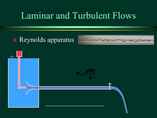
Overview • Asymmetric Nozzle Flow Features • Designs for Cleaning and Mixing • Submerged incompressible jets • Reynold’s Number, 6 E5 < Re < 1.2 E6 • Geometry, Parametric studies • New Results, Power imparted to fluid • Conclusions
Asymmetric Jet Flow Features • Wide variety found in the literature • Flat plate orifices, smooth interior nozzles • Incompressible, Compressible transonic • Mainly experimental studies • Simplified non-circular vortex ring studies • Very few CFD studies
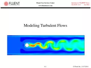
Typical Asymmetric Jet Flows • Eccentric vortex “ring” axes switch positions (called “vortex induction”). • Increase entrainment and mixing. • Shear layers asymmetric and change downstream. • Turbulence asymmetric and changes downstream.
Designs for Cleaning and Mixing • Submerged jets, Impinging jets • Specialized interior “fluted” transition • Application to Subterranean Drilling and Environmental Cleaning • Example: Jets for “fixed cutter” PDC (Polycrystalline Diamond Compact) drill bits with 3 to 8 nozzles
CFD Considerations • High levels of recirculation and mixing require a good turbulence model. • Interior nozzle geometry is important. • Large length scale differences between flows internal and external to the jet suggest adaptive solutions. • Hp-adaptive methods are most efficient.
ProPhlex CFD Software • Three-dimensional Navier-Stokes Eqs • Turbulent “K - ”closure • Adaptive - hp finite element system: • Automatic mesh refinement / de-refinement • Automatic degree enrichments (1- 8 degree) • Ainsworth-Oden N-S error estimator • Specialized kernel for auxiliary calculations
Fluted Nozzle Geometries • Non-circular interior cross-sections • Sharp interior edges “parallel” to flow direction • Terminate with sharp transverse edges at outlet area • Controlled area changes to enhance shear stresses at the outlet
Fluted Nozzle Hydraulics • Less than hydrostatic face pressures on impingement surface • Increases local re-circulation • Increases mass entrainment • Increases hydraulic power • Changes location of peak turbulence
Exit Flow Differences • Velocity varies in magnitude and direction over outlet area • Velocity has additional components • Pressure varies over area • Shear stresses vary over area • Shear stresses contribute to power
Power Imparted to Fluid • Power per unit area: The product of the velocity vector and force per unit area. • Fluid Power: Integral of this product over the nozzle inflow and outflow areas. • Circular Jet:reduces to the product of the pressure drop and flow rate. • Significantly increases in asymmetric jets, by a factor of 2 to 3.
Primary Variables • Velocity vector: Vj • Stress tensor: kj • Pressure and shear stress tensors • pkj = pkj,kj = pkj + kj • Area normal vector: nk • Surface force vector: Fj = kj nk • Power per unit area: P = Vj Fj • Volumetric flow rate:Q
Stress Tensors • kj = p kj + kj stress tensor • kj= µt(Vk,j + Vj,k) shear stresses • Vk is the velocityvector • Turbulent viscosity, µt, changessignificantly with location, µt K2 /
Integrals Over Exit Area • Net Flow rate, Q: Q = A Vk nkdA • Net Power, P:P = A Vk FkdA • Circular: Vk, nk, Fk are parallel vectors • Asymmetric: Vk, nk, Fk are not parallel, more terms appear in Fk = jknj • Asymmetric jet powerishigher for same A, Q, p. Correlates to P = cQp, c >1.
Engineering Design Differences Exit Flow Description: Cir Asy • Velocity, Vk, parallel to axis, nk yes no • Velocity constant over the area yes no • Pressure, p, constant over area yes no • Rapid change in shear stress, Tkj no yes • Surface force, Fk, parallel to nk yes no • Product of Vk & its gradient is 0 yes no • Power = c Qp c=1 c>1
Power Calculations via CFD • CFD post-processing was modified to numerically integrate the power contributions over the nozzle inlet and outlet surfaces. • Applying to a 3-D model of an axisymmetric jet gave P = 0.98 Q p where 1-D result isP = Q p. • Applying to a 3-D model of an asymmetric jet gave P = c Q p where 2 < c < 3.
Asymmetric Jet Net Power Increase(For corrected areas.) Size (d*32) 7 8 9 10 11 12 13 % Increase 79 84 88 91 95 98 100 Size 14 15 16 17 18 19 20 % Increase 101 103 105 107 108 109 109 Asymmetric jets impart more power to the fluid for the same flow rate and pressure drop.
Drilling Nozzle Parametric Studies • Fluted transition exit shapes • Oval (2 lobes @ 180), 3 lobes @ 120, Cruciform (4 lobes @ 90), 2 lobes @ 60, single flute to offset circular outlet, etc. • Distance to impingement surface • Volumetric flow rates
Unique Impingement Pressures • Regions of less than hydrostatic pressure • Locations controlled by asymmetric shape • Peak value 15-20% of stagnation pressure
Example Asymmetric Jet Flows • Pressures • Velocity Fields • Turbulence • Power levels • Related Lab and Field Results
Effect on PDC Rate of Penetration(bychanging to asymmetric fluted jets)
Conclusions • Asymmetric jets give higher entrainment, mixing and turbulence levels. • They impart more power to the fluid and have unusual pressure distributions. • CFD is necessary to understand them. • A number of industrial flow applications are apparent and merit study.