Planes, Polygons and Objects
This overview explores the foundational concepts of polygons and polyhedra in computer graphics, emphasizing the importance of polygonal meshes over simple spheres for representing complex shapes. Key aspects covered include the definition of polygons, the derivation of plane equations, and how polygons can be categorized as convex or concave. The text also delves into the construction and representation of polyhedra, including indexed face sets and winged edge data structures, highlighting their advantages in efficient rendering and complex operations such as ray-polygon intersections.

Planes, Polygons and Objects
E N D
Presentation Transcript
Planes, Polygons and Objects ©Anthony Steed 1999-2005
Overview • Polygons • Planes • Creating an object from polygons
No More Spheres • Most things in computer graphics are not described with spheres! • Polygonal meshes are the most common representation • Look at how polygons can be described and how they can used in ray-casting
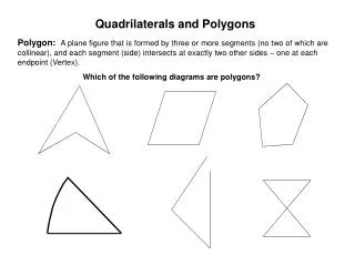
Polygons • A polygon (face) Q is defined by a series of points • The points are must be co-planar • 3 points define a plane, but a 4th point need not lie on that plane
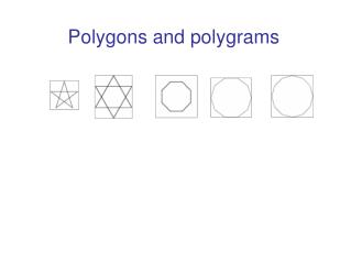
Convex, Concave • Convex • Concave • CG people dislike concave polygons • CG people would prefer triangles!! • Easy to break convex object into triangles, hard for concave
Equation of a Plane • a,b,c and d are constants that define a unique plane and x,y and z form a vector P.
p 2 p 1 p p 0 Deriving a,b,c & d (1) • The cross product defines a normal to the plane • There are two normals (they are opposite) • Vectors in the plane are all orthogonal to the plane normal vector
Deriving a,b,c & d (2) • So p-p0 is normal to n therefore • But if n = (n1,n2,n3) • a= n1 b= n2 c= n3 (n.p) • d = n.p0 = n1*x0 + n2*y0 + n3*z0
Half-Space • A plane cuts space into 2 half-spaces • Define • If l(p) =0 • point on plane • If l(p) > 0 • point in positive half-space • If l(p) <0 • point in negative half-space
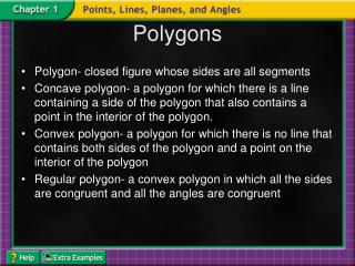
Polyhedra • Polygons are often grouped together to form polyhedra • Each edge connects 2 vertices and is the join between two polygons • Each vertex joins 3 edges • No faces intersect • V-E+F=2 • For cubes, tetrahedra, cows etc...
Example Polhedron v 4 • F0=v0v1v4 • F1=v5v3v2 • F2=v1v2v3v4 • F3=v0v4v3v5 • F4=v0v5v2v1 • V=6,F=5, E=9 • V-E+F=2 e7 v 3 e9 e5 e6 e8 v 5 e3 v 2 e4 e2 v o v 1 e1
Representing Polyhedron (1) • Exhaustive (array of vertex lists) • faces[1] = (x0,y0,z0),(x1,y1,z1),(x3,y3,z3) • faces[2] = (x2,y2,z2),(x0,y0,z0),(x3,y3,z3) • etc …. • Very wasteful since same vertex appears at 3(or more) points in the list • Is used a lot though!
Representing Polyhedron (2) • Indexed Face set • Vertex array • vertices[0] = (x0,y0,z0) • vertices[1]=(x1,y1,z1) • etc … • Face array (list of indices into vertex array) • faces[0] = 0,2,1 • faces[1]=2,3,1 • etc ...
v 4 v 3 5 v v 2 v o v 1 Vertex order matters • Polygon v0,v1,v4 is NOT equal to v0,v4,v1 • The normal point in different directions • Usually a polygon is only visible from points in its positive half-space • This is known as back-face culling
Representing Polyhedron (3) • Even Indexed face set wastes space • Each face edge is represented twice • Winged edge data structure solves this • vertex list • edge list (vertex pairs) • face list (edge lists)
The Edge List Structure • Edge contains • Next edge CW • Next edge CCW • Prev edge CW • Prev edge CCW • Next face • Prev face • Next vertex • Prev vertex
Advantages of Winged Edge • Simple searches are rapid • find all edges • find all faces of a vertex • etc… • Complex operations • polygon splitting is easy (LOD) • silhouette finding • potentially efficient for hardware • etc…
Building the WE • Build indexed face set • Traverse each face in CCW order building edges • label p and n vertices, p and n faces and link previous CCW edge • we fill in next CCW on next edge in this face • we fill in next CW and prev CW when traversing the adjacent face.
Exercises • Make some objects using index face set structure • Verify that V-E+F=2 for some polyhedra • Think about testing for intersection between a ray and a polygon (or triangle)
Recap • We have seen definition of planes and polygons and their use in approximating general shapes • We have looked at two data structures for storing shapes • Indexed face sets • Winged edge data sets • The former is easy to implement and fast for rendering • The latter is more complex, but makes complex queries much faster • It is possible, though we haven’t shown how, to convert between the two