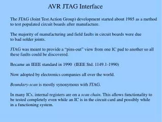
JTAG Programming Guide for ECE 353 Laboratory
This guide provides step-by-step instructions for programming JTAG devices in the ECE 353 Computer Systems lab. Using Quartus II, users will learn to set up hardware connections via parallel or USB interfaces, ensuring safe practices like disconnecting the 4MHz clock before programming. Follow the outlined procedures to detect the hardware, load the appropriate POF file, and verify programming success. For additional resources, links to Altera's documentation are included. Ensure all connections are in order, and consult with TAs for assistance as needed.


JTAG Programming Guide for ECE 353 Laboratory
E N D
Presentation Transcript
How to Program with JTAG ECE 353 – Computer Systems lab I Mike O’Malley Tom Stack September 20th 2005
Click “Add Hardware” For the parallel port version select ByteBlasterMV The printer port (LPT1) For the USB version TBD Click “Ok” Click “Close” Hardware Setup
Schematic for JTAG programming http://www.altera.com/literature/an/an095.pdf http://www.altera.com/literature/ds/m7000.pdf
WARNING! DISCONNECT 4Mhz CLOCK BEFORE ATTACHING TO PROGRAMMER
Quickly Check for burning chip Unplug Power Check connections Is the clock unplugged? Ask the TA for assistance Bad!
Navigate to your project folder Select the .pof file created from compilation Click “Open” Select your .pof file
All Green is good Unplug power Unplug programmer Connect clock Connect Power Red is bad Check connections Ask TA for help Programming Complete