Download
1 / 24
240 likes | 436 Vues
ROAD TO CLIMATE FRIENDLY CHILLERS Hydrocarbons & Absorption Chillers Systems: Development & Potential Dr. Alaa Olama Sept. 2010 , Cairo, Egypt. CONTENTS: 1- Hydrocarbon fired Absorption Chiller & Heat ratio 2- Difference between HR (COP) Abs. & COP V.C.

E N D
ROAD TO CLIMATE FRIENDLY CHILLERS Hydrocarbons & Absorption Chillers Systems: Development & Potential Dr. Alaa Olama Sept. 2010 , Cairo, Egypt
CONTENTS: 1- Hydrocarbon fired Absorption Chiller & Heat ratio 2- Difference between HR (COP) Abs. & COP V.C. 3- How did H.R (COP) improve dramatically. 4- Conclusion
Definition of COP (HR) of Absorption Chillers COP(LP)= (Refrigeration capacity/(Gas Low calorific value*Gas consumption) COP(HP)= (Refrigeration capacity/(Gas High calorific value *Gas consumption)
Overall efficiency of a power station: * Efficiency at Refrigeration plant boundary becomes 25 to 50 %
History of absorption chiller-heater 1.1 1.07 0.75 0.93~0.96 1.3 0.80 1.2 1.35 1.6以上 2005.2Kyoto Protocol History of development for Gas direct fired absorption chiller
5.High performanceheat transfer tube 2.RefrigerantCooler 6.Exhaust heat-exchanger 3.Dual absorptionDual evaporation 7.Larger Heat transferarea on ABS. EVP. RFD 8-Efficiency improvedon High stage GEN. 4.Condensed refrigerantheat-exchanger Key technology to improve the efficiency RCD 1.Improved solutionheat-exchanger RED
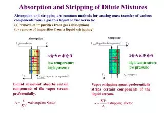
Low temp. High temp Plate heat-exchanger Key technology of improvement 1- Improvement on efficiency of solution heat-exchanger • Solution heat-exchanger Shell & Tube typeheat-exchanger ☆Advantage ・ Better heat transfer performance compared to S&T ◎More compact ・ Less solution retained
CONDS. 37℃ Refrigerant 38℃ Ref. cooler 36.5℃ EVP. (9℃) ABS. 32℃ Cooling W Key technology of improvement 2- Refrigerant cooler Cooling down the refrigerant back from condenser, to reduce the load on Generator, to get better efficiency ↓ 33℃
Key technology of improvement Enable to reduce circulating flow Less heating calorie at Generator,thus better efficiency 3- Dual Absorption, Dual Evaporation Cycle Upper stage:Low pressure in ABS. / EVP.Lower stage:High pressure in ABS. / EVP. ☆AdvantageBigger concentration difference of solution, by separating ABS. & EVP. to 2 stages
Key technology of improvement 4- Condensed refrigerant heat-exchanger 90℃ 44℃ Condenser(38℃) Low stage GEN. Heat from Low GEN.⇒Steam from High GEN. Condensedrefrigerant 78℃ 36℃ Heat recovery on High temp. Refrigerant back from low GEN. and weak solution, to get better efficiency Condensed refrigerantheat-Exchanger High temp. H-exchanger Low temp. H-exchanger S.P. Weak solution
5- High Performance heat transfer tube Key technology of improvement
6- Exhaust heat-exchanger(Air pre-heater) Air Pre-heater 75℃ High GEN. 155℃ Key technology of improvement Exhaust The gas consumption reduced by pre-heating the air supply to the Burner. 165℃ Air supply 20℃ Natural Gas
Key technology of improvement 7- Larger Heat transfer area on ABS. EVP.
Key technology of improvement 8- Efficiency improved on High stage GEN.
Improved solution heat-exchanger COP1.22 Exhaustheat-exchanger RED Designed based on COP1.29 machine Refrigerant cooler Reached COP1.35 with Exhaust heat-exchanger Solution flow regulation Dual ABS. / EVA. Efficiency improved High GEN. increased KA value, on CND. ABS. Improved solutionheat-exchanger Large head of chilled water (Δ8℃) Exhaustheat-exchanger Condensed ref. heat-exchanger RFD +0.05 +0.02 +0.085 +0.035 +0.015 +0.04 +0.06 +0.015 +0.02 COP1.00 COP1.29 COP1.35 Key technology of improvement Improvement of COP by each technology +
Conclusions:- 1- When comparing The overall thermal efficiencies ,it is important to compare the efficiency of mechanical vapour compression systems (electric chillers) to the efficiencies of vapour compression systems ( absorption chillers) , starting at the boundary of supply to the power station(natural gas ) and the boundary of supply of natural gas at the absorption chillers burner, otherwise the comparison cannot be fair. 2- When this is done ,the difference in efficiencies is then quite close , taking into consideration that few power stations in Egypt have high thermal efficiencies. 3- Therefore the use of natural gas in large central air conditioning projects is economically sound since the saving in investment cost for power plant is considerable. (1)
Conclusions(Cont.):- 4- Shaving electrical peak loads in summer can only be achieved by the use of natural gas fired air conditioning system. 5- legislation exists in many countries that prohibit the use of electrical energy in air conditioning over a certain refrigeration tonnages (over about 1000 TR) This is the case in Japan , South Korea & lately the United Arab Emirates. The aim of the legislation is to preserve electric power for applications where there are not other alternative sources of energy . (2)