Special Design Report
100 likes | 194 Vues
This report outlines the need for additional PWM channels, the design process, and results achieved. Implementing 2 additional channels is detailed with a focus on locomotion using Altera MAX7032 CPLD. The design includes 3 settings (Forward, Reverse, Stopped) for each channel selection. A 1 MHz clock, Atmel Mega163 microcontroller, and VHDL development are discussed, showcasing successful waveform tests with servos.

Special Design Report
E N D
Presentation Transcript
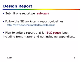
Special Design Report IMDL Summer 2002 Matthew Chernosky July 11, 2002
Overview • Additional hardware Pulse Width Modulation channels • Need for additonal PWM channels • Design • Results
Need for additional channels • Atmel ATMega163 • 3 PWM channels built-in • Motion • Requires 2 channels (left and right) • Golf ball pickup • Needs more than one channel
Design • 2 additional channels to be implemented • Channels used for locomotion • Altera MAX7032 CPLD • Development in VHDL
Design • 3 Settings for each channel • Forward • Reverse • Stopped • A 2-bit wide input bus selects desired setting for each channel • 4 output port pins of uP
Design 1 MHz oscillator Atmel Mega163 Chan A select Altera MAX7032 PWM A Out PWM B Out Chan B select CPLD Microcontroller
Design Reset 15-bit counter Logic FF PWM A 1 MHz clock FF PWM B Chan A select Chan B select CPLD
VHDL ENTITY motor_pwm_580 IS PORT( clk : in STD_LOGIC; PWM_IN_A: in STD_LOGIC_VECTOR(1 downto 0); PWM_IN_B: in STD_LOGIC_VECTOR(1 downto 0); PWM_OUT_A: out STD_LOGIC; PWM_OUT_B: out STD_LOGIC ); END motor_pwm_580;
VHDL cnt: PROCESS (clk) BEGIN IF (clk = '1' and clk'EVENT) THEN if (count < COUNT_MAX) then -- increment counter count <= count + 1; else -- reset counter when COUNT_MAX reached count <= COUNT_RST; end if; END IF; END PROCESS;
Results • Oscilliscope waveform tests • Works with servos 1.75 ms 20 ms