Download
1 / 40
400 likes | 420 Vues
Explore the comprehensive plan and parameters for enhancing the RF system of SuperKEKB, focusing on addressing challenges related to high beam current and stability. The workshop summary includes potential strategies, modifications, and improvements needed for successful operation beyond designated beam current levels.

E N D
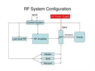
RF System for SuperKEKB K. AKAI Jan. 20, 2004 SuperB Factory Workshop Hawaii Contents: ◆ Base plan ◆ ARES and SC cavities ◆ High beam current and measures ◆ Crab cavity ◆ Construction
Base plan • KEKB RF system • Excellent performance at 1.8A (LER) and 1.2A (HER) shows potential for operating beyond the design beam current of KEKB. • Strategy for SuperKEKB: • Adopt the same RF frequency as KEKB and use the existing RF system as much as possible, with improvements as necessary to meet the requirements for SuperKEKB. • If this scheme is feasible: • Construction cost is greatly reduced. • Technical uncertainties are relatively small. • Important issues: • Very high beam current (4 times as KEKB) • Short bunch length of 3mm. RF System for SuperKEKB (K. Akai)
RF parameters for SuperKEKB RF System for SuperKEKB (K. Akai)
Problems to be solved • Strong longitudinal CBI due to a large detuning of the accelerating mode, even with ARES and/or SCC. • Growth rate = (0.3 ms)-1 • CBI due to HOM and other parasitic modes • Large HOM power in each cavity • HOM dampers • Strengthening of RF power is required • 4 times as high as KEKB RF System for SuperKEKB (K. Akai)
Measures for CBI due to fundamental mode • Two measures will be taken: • (1) Modify LER-ARES • Remodel the A-C cavity of the ARES to increase the stored energy further. • The -1 mode growth rate is reducedfrom (0.3ms)-1 to (1.6ms)-1. • No modification on the HER-ARES: majority of the driving impedance in HER is attributed to SCC. • (2) RF feedback (-1 mode damper) • The growth time of 1.6ms (LER) and 1ms (HER) is still faster than the radiation damping time by a factor of 20. • The instability will be suppressed by the -1 mode damper. • The -2 mode also needs to be suppressed by the feedback. RF System for SuperKEKB (K. Akai)
Modification of LER-ARES • The ARES in LER will be remodeled to increase the stored energy further. • By enlarging the coupling hole between the A-C cavities, Us/Ua will be increased from 9 to 15. • Storage cavity is reused. Coupling impedance for the p/2 mode T. Kageyama, et. al. Growth rate as a function of Us/Ua RF System for SuperKEKB (K. Akai)
The existing -1 mode damper at KEKB • The -1 mode CBI occurs at more than 1A in KEKB-LER. • It is suppressed by the -1 mode damper. • The damping time of 1 ms is required for SuperKEKB. FB OFF FB ON S. Yoshimoto, et. al. RF System for SuperKEKB (K. Akai)
CBI due to the 0 and p modes of ARES • The large detuning of the A-cavity gives rise to imbalance of the 0 and p mode impedance. • Longitudinal CBI can be excited. The growth time is 4ms. • It is outside the bandwidth of the klystrons. Top: Re [Z//] of the 0 and p modes Bottom: Re [Z//] imbalance R+-R- RF System for SuperKEKB (K. Akai)
Summary of CBI due to RF cavities Longitudinal Longitudinal bunch-by-bunch FB is needed. Required damping time is 4ms. Transverse The instability can be suppressed by the present transverse bunch-by-bunch FB. RF System for SuperKEKB (K. Akai)
ARES HOM dampers RF System for SuperKEKB (K. Akai)
HOM power of LER-ARES SuperKEKB WG damper KEKB GBP damper RF System for SuperKEKB (K. Akai)
Improve the ARES-HOM dampers • The waveguide dampers • High power tested up to 3.3 kW/bullet (26 kW/cavity). • Upgrade needed to 80 kW/cavity. • Will be tested at higher power with a new high power source. • The number of bullets/waveguide will be increased. • The grooved beam pipe dampers • High power tested up to 0.5 kW/groove (2 kW/cavity). • Upgrade needed to 20 kW/cavity. • A new type of damper? Such as a winged chamber with SiC bullets? Y. Suetsugu, et. al. RF System for SuperKEKB (K. Akai)
SCC HOM power and beam pipe • Present HOM dampers in KEKB have been operated up to 12 kW/cavity. RF System for SuperKEKB (K. Akai)
Improve the SCC-HOM damper • The present HOM damper will be bench tested to see its performance limit. • The points are effective cooling, surface temperature, and outgas. • If SBP side damper works at 20kW, the present dampers may be used for Super-KEKB. If not, modification or new design of dampers is necessary. • In addition, the beam pipe diameter will be changed to 220 mm to reduce the loss factor. RF System for SuperKEKB (K. Akai)
Strengthening of RF power • Required RF power provided to beam is 18 MW (LER) and 16 MW (HER), four times as high as those of KEKB. • The required RF voltage is relatively low. • The number of cavities should be kept as small as possible to reduce the total impedance in the ring. • Change to one ARES/klystron configuration. • KEKB: two ARES/one klystron • The input power to each cavity will be nearly doubled. • The number of klystrons will be more than doubled. RF System for SuperKEKB (K. Akai)
Loss factor and Number of RF units • Required number of RF units is expressed as: 28 unit kothers is loss factor except cavities, and Pbo is beam power by each unit. RF System for SuperKEKB (K. Akai)
Input couplers • Performance at KEKB • Operating typically at 300-350 kW/coupler (ARES, SCC). • The ARES coupler tested up to 950 kW (through). • The SCC coupler tested up to 800 kW (through), 300 kW (total reflection). • Requirement for SuperKEKB • Operation at 900 kW/coupler (ARES), 500 kW/coupler (SCC). • Plans and prospect • The present couplers can be probably used in SuperKEKB. • Improvements and tests planned. • A new high power test setup is being constructed. • R&D to suppress multipactoring (TiN coating) is going on. • Increasing the operating power of SCC > 400kW in 2004. RF System for SuperKEKB (K. Akai)
Number of RF units RF System for SuperKEKB (K. Akai)
New buildings needed RF System for SuperKEKB (K. Akai)
Construction plan • Before 2008 • Construct 14 units of RF system • To change to 1 ARES/1 klystron configuration • 2 RF stations for Crab crossing experiment @Nikko • After 2008 • Construct 18 units of RF system • Fabricate 10 more ARES’s • Fabricate 4 SCC’s • Construct RF system for Crab cavities RF System for SuperKEKB (K. Akai)
Schedule RF System for SuperKEKB (K. Akai)
Crab crossing Palmer for LC (1988) Oide and Yokoya for storage rings (1989) Recent simulations by Ohmi showed significant increase of luminosity by several times by the crab crossing. RF System for SuperKEKB (K. Akai)
Parameters for the crab crossing RF System for SuperKEKB (K. Akai)
Accelerating cavities Operating mode (TM010) is the lowest frequency mode. Any parasitic mode (HOM) has higher frequency than the operating mode. Wave guides or beam pipe with cut-off frequency higher than the operating mode can damp all HOM’s. (ARES, SCC, PEP-II cavity, etc) Crab cavity Operating mode (usually TM110) is NOT the lowest frequency mode. There exists lower frequency parasitic mode(s). Wave guides can damp higher frequency modes. However, special care is needed for the lower frequency modes. Damping parasitic modes RF System for SuperKEKB (K. Akai)
Original crab cavity • Squashed cell operating in TM2-1-0 (x-y-z) • Coaxial coupler is used as a beam pipe • Designed for B-factories (1〜2A) RF System for SuperKEKB (K. Akai)
Crab cavity with 10A beam • The original cavity is designed for 1 〜 2A beam • Simple structure, suitable for SC → High kick voltage is obtained by one cavity. • Sufficient damping of parasitic modes. • Not necessarily optimized for a 10 A beam. • Possible problems at 10A • Large HOM power (200kW) • Loss factor is not very small, because the radius of coaxial beam pipe can not be widely opened. • Additional loss factor comes from the absorber on wide beam pipe. • Much heavier damping of HOM’s may be needed, particularly for horizontal polarization of transverse modes (large bx_crab). • A new crab cavity has been designed, which can be used at 10A. RF System for SuperKEKB (K. Akai)
Design concept of new crab cavity • Squashed cell operating in TM2-1-0 (same). • Waveguide dampers are attached. • Much heavier damping of parasitic modes can be obtained. • Larger HOM power is allowed for the dampers. • Coaxial dampers are used, but not as a beam pipe. • The TM1-1-0 is well damped. • Loss factor is reduced since widely opened beam pipes can be used. • Optimization has been carried out for both the SC and NC versions independently. RF System for SuperKEKB (K. Akai)
Schematic drawing of new crab cavity • (Left) The cross-shaped waveguide dampers and coaxial dampers are attached at the squashed-cell. • (Right) Cross section of the coaxial damper at the cut plane of Y-Y’. RF System for SuperKEKB (K. Akai)
New crab cavity (1/4 cell) K. Akai and Y. Morita, to be submitted. RF System for SuperKEKB (K. Akai)
Coupling impedance Ohm/m Ohm Crabbing mode Lower frequency mode Horizontal Longitudinal RF System for SuperKEKB (K. Akai)
Comparison of cavities for SuperKEKB New crab cavity has advantages for Super-KEKB, especially in LER. Original crab cavity could be used in HER, if HOM absorber is OK with 50kW. RF System for SuperKEKB (K. Akai)
Summary of new crab cavity • Parasitic modes are sufficiently damped. • The lower frequency mode is also damped. • Instability can be suppressed with the present FB system, even at a beam current of 10A. • The problem for the dampers due to a large parasitic power is greatly eased: • Loss factor of the cell is reduced. • The absorbers do not contribute to the loss factor. • The parasitic power to each damper is further reduced since it is divided into the waveguide and coaxial dampers. • The new crab cavity can be used in SuperKEKB. RF System for SuperKEKB (K. Akai)
Summary of SuperKEKB RF system • Base plan: • The existing RF system will be used as much as possible, with improvements as necessary. • The ARES (LER, HER) and SCC (HER) will be used. • CBI due to the accelerating mode • LER-ARES will be modified, that eases the growth time from 0.3ms to 1.6ms. • The -1 mode damper will suppress the CBI with a growth time of 1 ms. • HOM dampers • Performance limit of the present HOM dampers will be tested. • A new HOM damper may by necessary, particularly for the GBP damper. • Large RF power • Improvement of the couplers will continue to double the operating power. • The number of RF unit will be doubled. • Crab cavity • A new crab cavity is proposed, which can be used at 10 A. • The design is completed. It has sufficient property for SuperKEKB. RF System for SuperKEKB (K. Akai)
Base plan assumed Same RF frequency as KEKB Use ARES (full set) Construction Fabricate a klystron and an ARES cavity. An existing power supply (B-type) will be moved. High-power and low-level system: partly new, partly reused. Total cost is about 2.4 Oku-en. (Building is not included.) RF-related parameters RF system for Damping Ring RF System for SuperKEKB (K. Akai)
Impedance-related issues Loss factor of LER (Suetsugu, Shibata, Stanic, Kageyama, Akai) RF System for SuperKEKB (K. Akai)
Cost estimation • Total cost = 111.2 Oku-yen, including • 32 klystrons • 15 power supplies • Evaporative cooling system for klystron collector • 32 High-power and Low-level systems • 20 existing ARES’s to be modified • 10 new ARES’s for LER • 4 additional SCC’s for HER • RF system for Crab cavities • R&D and Beam tests • Cost for related infrastructures such as buildings, electricity, cooling system are not included. RF System for SuperKEKB (K. Akai)