
The Xerographic Printing Process for Laser Printing
E N D
Presentation Transcript
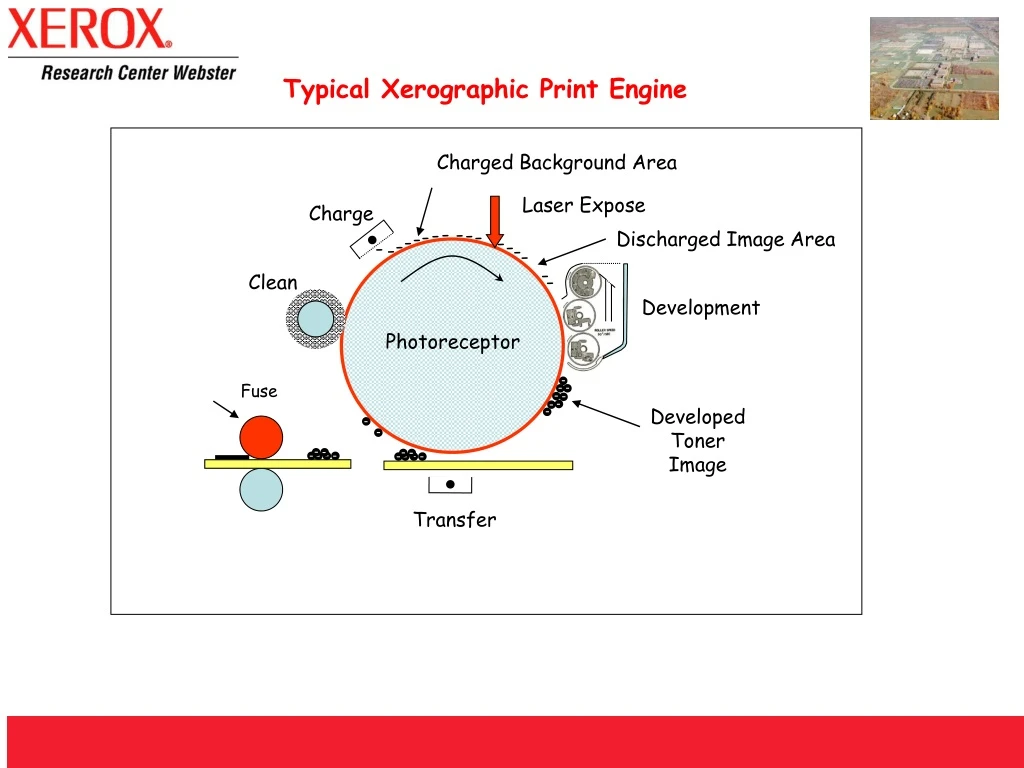
Typical Xerographic Print Engine Charged Background Area Laser Expose Charge - - - - - - - Discharged Image Area - - - - - - - - - - Clean Development Photoreceptor Fuse Developed Toner Image Transfer
The Xerographic Process Imaging 5) Cleaning 2) Exposing 1) Charging Output Photoreceptor 3) Developing 4) Transferring Fusing
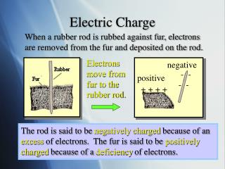
1) Charging Charging prepares the Photoreceptor. In charging, a uniform electric charge is deposited on the surface of the Photoreceptor. There are two types of charging technology: contact and non-contact. Each has pros and cons that need to be considered for each engine type and market. Imaging Imaging converts the computer data or the original into an optically projected image or digitally halftoned representation of the image. 2) Exposing The exposing process causes the level of electrical charge on the photoreceptor surface to change to correspond with the desired image. After exposure, the electrical charge on the photoreceptor surface which represents the lines, letters, or other forms differs from the charge in the non-image areas. Exposure is mostly done using laser beam, light emitting doide (LED) in today’s machines. Older engines used a projected image using light and various lens. Xerographic Process
3) Developing Developing deposits particles of Toner (dry ink) on the Photoreceptor. This is accomplished by first applying a charge to the toner particles. Due to this charge, toner only clings to the areas of the photoreceptor which correspond to the image. After development, a toner image is visible on the photoreceptor. There are many different development technologies used in today’s powder marking engines. 4) Transferring The purpose of transfer is to bring the paper into contact with the photoreceptor so that the toner image can be transferred to a substrate. The transfer step involves applying a charge to the substrate so that toner is electrostatically removed from the photoreceptor surface and attracted to the substrate. After transferring, some residual toner remains on the surface of the photoreceptor. In some architectures, two transfer steps are needed to get toner from an intermediate belt or drum to the paper. Others transfer toner directly to the paper, without an intermediate.
Fusing The Fusing step heats the toner particles, causing the particles to flow together as they melt onto the surface of the paper. After fusing, the image sticks permanently to the paper. 5) Cleaning The Cleaning step (sometimes includes Discharge) removes the residual charge of the image that was left on the photoreceptor (P/R) after transfer. Discharge can be accomplished by applying light or a neutralizing charge to the photoreceptor so that the residual toner no longer clings to the photoreceptor. Cleaning then mechanically removes the residual toner from the P/R. This is usually accomplished using brushes, blades, rolls, or some combination of the three. Once the Photoreceptor is clean, we are ready to repeat the overall process.
Example Architectures Multipass/Cyclic Architecture Tandem Color using Intermediate Transfer Architecture (above and below) Image on Image Architecture