Fuel Induction Systems for SI Engines
350 likes | 362 Vues
Fuel Induction Systems for SI Engines. P M V Subbarao Professor Mechanical Engineering Department. The Pace of Net Heat Addition Influence the Area of the Engine Cycle …. Induction of Fuel in SI Engine.

Fuel Induction Systems for SI Engines
E N D
Presentation Transcript
Fuel Induction Systems for SI Engines P M V Subbarao Professor Mechanical Engineering Department The Pace of Net Heat Addition Influence the Area of the Engine Cycle …..
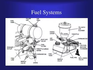
Induction of Fuel in SI Engine • The task of the engine induction and fuel systems is to prepare from ambient air and fuel in the tank an air-fuel mixture that satisfies the requirement of the engine. • This preparation is to be carried out over entire engine operating regime. • In principle, the optimum air-fuel ratio for an engine is that which give the required power output with the lowest fuel consumption. • It should also ensure smooth and reliable operation. • The fuel Induction systems for SI engine are classified as: • Carburetors. • Throttle body Fuel Injection Systems. • Multi Point Fuel Injection Systems.
pthroat p1 > p2s > pthroat p1 p1 p2s p
Real Flow Through A Venturi pthroat p2a <p2s p1 p1 p2a p
Real Air Flow Through Venturi Where Fuel Flow Through Orifice
Artificial Induction of Fuel • The fuel-injection systems for conventional spark-ignition engines inject the fuel. • There are both mechanical and electronically controlled injection systems. • Better volumetric efficiency • More uniform fuel distribution • More rapid response to changes in loading conditions • More precise control of the equivalence ratio.
Merits of Fuel Injection in the SI Engine • Absence of Venturi – No Restriction in Air Flow/Higher Vol. Eff./Torque/Power • Hot Spots for Preheating cold air eliminated/Denser air enters • Manifold Branch Pipes Not concerned with Mixture Preparation (MPI) • Better Acceleration Response (MPI) • Fuel Atomization Generally Improved. • Use of Greater Valve Overlap • Use of Sensors to Monitor Operating Parameters/Gives Accurate Matching of Air/fuel Requirements: Improves Power, Reduces fuel consumption and Emissions • Precise in Metering Fuel in Ports • Precise Fuel Distribution Between Cylinders (MPI
Merits (Continued) • Fuel Transportation in Manifold not required (MPI) so no Wall Wetting • Fuel Surge During Fast Cornering or Heavy Braking Eliminated • Adaptable and Suitable For Supercharging (SPI and MPI) • Increased power and torque.
Modeling of Fuel injection • The models needs to predict the spray process, • the distribution and evaporation of droplets and • the fuel layer formation and transmission in the port. • The governing equations of motion and droplet evaporation are used to develop a model. • The rate of evaporation of liquid fuel is calculated by first determining the fuel mean drop diameter (SMD) and characteristic evaporation time τeva according below equation: where mlis the liquid fuel mvis the mass of the fuel vapor. eva is time factor
Time Factor • Time factor calculated based on the energy balance between the surrounding air and the liquid droplet and the assumption that the heat transferred is a fraction of the available energy. • The size of droplet and its energy will decide the rate of evaporation.
Droplet Size Distribution • The droplet size distribution in sprays is the crucial parameter needed for the fundamental analysis of the transport of mass, momentum and heat in evaporation. Engineering • Parameter determines the quality of the spray and consequently influences to a significant extent the processes of emissions in combustion. • Detailed experimental data is used to develop distribution functions. • To obtain the detailed quantitative information of the sprays, a two-component Phase Doppler Anemometry (PDA) is used. • This performs the simultaneous measurements of the droplet velocity and size and the volume flux.
Mean diameter distribution of droplets (micron) in 100 mm downstream and 300 Kpa, 25o C
Distribution of droplets velocity (m/s) in 100 mm downstream and 300 Kpa, 25o C
Frequency diagram of droplets mean diameter D is the droplet diameter and N is the normalized number distribution.
Physical Models for Spray Characterization Entropy of a group of droplets: where S is the information entropy, the name used when the information concept is applied to problems in physics and engineering. In this equation K is a constant and Piis the probability of the occurrence of a certain result, in terms of number fraction. Maximum feasible entropy corresponding to physical conditions will decide the droplet distribution.
Physical Constraints • The following physical and mathematical constraints must be obeyed: • The sum of all probabilities must be unity: (ii) the mass flow of sprayed liquid must be equal to the mass of all droplets produced per unit time: where n is the total number of droplets produced per unit time and mL is the liquid mass flux.