Download

1 / 44
440 likes | 622 Vues
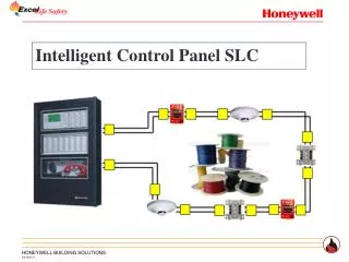
ECP Extinguishing Control Panel. Extinguishing Control Panel. General overview Technical overview. Extinguishing Control Panel. Extinguishing Control Panel. Applications Computer Suites Communication Centres Telecom Shelters Archives Document Stores. Extinguishing Control Panel.

E N D
Extinguishing Control Panel • General overview • Technical overview
Extinguishing Control Panel Applications • Computer Suites • Communication Centres • Telecom Shelters • Archives • Document Stores
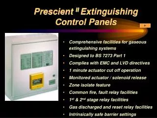
Extinguishing Control Panel • Designed to EN54: 2 & 4 for detection and alarm • Designed to BS7273: Pt1 for extinguishing control • Designed, manufactured and tested to ISO9001 • Over 25 years experience in extinguishing control • EMC and LV compliance
Extinguishing Control Panel • Fixed format 2 +1, 4 + 1 & 4 + 2 • Self contained with integral PSU • Fully programmable from the membrane fascia • Slider text inserts for translations • All critical I/O circuits are monitored • Clear precise information via LED indications • Flush mounting bezel available
Extinguishing Control Panel Membrane Fascia Three main areas • Panel status LED’s section • Extinguishing control & indications section(s) • Panel function controls section
Extinguishing Control Panel Membrane Fascia Panel Status LED Indications
Extinguishing Control Panel Membrane Fascia Extinguishing Control LED Indications Area #1
Extinguishing Control Panel Membrane Fascia Extinguishing Control LED Indications Area #1
Extinguishing Control Panel Membrane Fascia Extinguishing Control LED Indications Area #2
Extinguishing Control Panel Membrane Fascia Extinguishing Control LED Indications Area #2
Extinguishing Control Panel Membrane Fascia Control Panel Functions
Extinguishing Control Panel Membrane Fascia Control Panel Functions
Extinguishing Control Panel Membrane Fascia Controls - Extinguishing Areas
Extinguishing Control Panel Monitored Input Circuits
Extinguishing Control Panel Monitored Input Circuits
Extinguishing Control Panel Monitored Output Circuits
Extinguishing Control Panel Monitored Outputs
Extinguishing Control Panel Access Levels • Reference EN54:2 restrictions • Level 1 - Front Fascia • Level 2 - Via a programmable 4 digit pass code providing limited controls
Extinguishing Control Panel Access Levels • Level 3 - Via a fixed 4 digit pass code providing additional controls • Level 4 - Via a camlock enabling access inside the control panel & programming switch
Extinguishing Control Panel Programming Options
Extinguishing Control Panel How to program • Access level 4 (inside control panel) operate switch 1 leaf 2 to the on position • Panel enabled LED will pulse rapidly • Select required menu option 01, 02, 03, etc.
Extinguishing Control Panel How to program • Programming details as per the manual • Confirm selection by “Programme” button • Return switch 1, leaf 2 to the off position
Extinguishing Control Panel Programming Options Co-incidence Detection -02 (4+1 Version Only)
Extinguishing Control Panel Programming Options Fault Inhibit Release -06
Extinguishing Control Panel Compatibility • Detection devices - KFP conventional devices • Manual release units KFP devices • Alarm devices - bells, electronic sounders, beacons of KFP manufacture • KFP manufactured extinguishing equipment
Extinguishing Control Panel Peripheral equipment • Status indicators • Hold switches • Abort switches
Extinguishing Control Panel • Status indicators- SI-1 LED indications only- SI-2 LED indications & manual release unit- SI-3 LED indications, manual release unit & auto/manual key switch
Extinguishing Control Panel Peripheral equipment (cont’d) *(1) SI-2 or 3 only*(2) SI-3 only
Extinguishing Control Panel Peripheral equipment • Status indicators- 6 status indicators up to 1.2km away from the ECP- Flush mounted or surface mounted options- RS 485 communications over 2 core cable- Selectable for area A or area B coverage- Lamp test facility- Surface mounted version 123mm (w) x 123mm (h) x 64mm (d)- Flush mounted version 143mm (w) x 143mm (h)
Extinguishing Control Panel • Hold Switch- Red mushroom button, non-latching- IP 56 enclosure- 108mm (w) x 108mm (h) x 85mm (d)- Out of sequence monitoring by the ECP
Extinguishing Control Panel • Abort Switch- Red mushroom button, twist to release- IP 56 enclosure- 108mm (w) x 108mm (h) x 85mm (d)- Out of sequence monitoring by the ECP
Extinguishing Control Panel Technical Summary • Quiescent current ECP 2+1 77mA ECP 4+1 84mA ECP 4+2 93mA • Battery Calculations Quiescent current x battery degradation factor x 24 hours + half hour alarm time x alarm load x battery degradation factor Q1 x 1.25 x 24 + 0.5 x Al x 1.25
Extinguishing Control Panel Technical Summary • ECP 2+1 Example 0.077mA x 1.25 x 24 + 0.5 x 1.0 x 1.25 2.31 + 0.625 2.935 A/H Note: 7 A/H battery space available
Extinguishing Control Panel Technical Summary • ECP 4+1 Example 0.084mA x 1.25 x 24 + 0.5 x 1.0 x 1.25 2.52 + 0.625 3.145 A/H Note: 7 A/H battery space available
Extinguishing Control Panel Technical Summary • ECP 4+2 Example 0.093mA x 1.25 x 24 + 0.5 x 1.0 x 1.25 2.79 + 0.625 3.415 A/H Note: 7 A/H battery space available
Extinguishing Control Panel Technical Summary • End of line resistors Sounder circuits 10K Detection zones 3K9 • Dimensions ECP 2+1 438 (w) x 128 (d) x 398 (h) ECP 4+1 438 (w) x 128 (d) x 398 (h) ECP 4+2 438 (w) x 128 (d) x 398 (h) • Weight ECP 2+1, ECP 4+1 & ECP4+2 7.2Kg
Extinguishing Control Panel Fuse Details Note: Sub minature fuses are of the plug in type which have a 5mm pitch and are the F type (quick blow). The leads of the fuses will need to be cut down prior to being mounted in their sockets.
Extinguishing Control Panel Internal Controls
Extinguishing Control Panel Internal Indications
Extinguishing Control Panel Status Indicators SW1 - Momentary push button for micro-processor resetSW2 - Momentary push button for LED test
Extinguishing Control Panel Status Indicators The status indicators have a terminating resistor network for the RS485 communications, the jumper selection must be as detailed below. The ECP RS485 driver card for the status indicators has two way DIL switch SW1 located on the board. With leaves 1 & 2 in the ON position the board will drive in both directions. With leaves 1 & 2 in the OFF position the board will drive in one direction only.
Extinguishing Control Panel Flush mounting bezel