High Speed Digital Design Project
High Speed Digital Design Project. SpaceWire Router. Part A Final Presentation. By: Asaf Bercovich & Oren Cohen Advisor: Mony Orbach Semester: Winter 2007/2008 2-Semester Project Date: October 2008. Project Goal.

High Speed Digital Design Project
E N D
Presentation Transcript
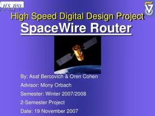
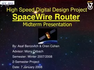
High Speed Digital Design Project SpaceWire Router Part A Final Presentation By: AsafBercovich & Oren Cohen Advisor: MonyOrbach Semester: Winter 2007/2008 2-Semester Project Date: October 2008
Project Goal • Designing a SpaceWireSwitch Core (Router) compatible to ECSS-E-50-12A Standard. • The design will be coded and simulated using Xilinx development enviroment and implemented onto a Xilinx VirtexII-Pro FPGA.
System Topology Router
System Topology • Full duplex • Low latency • Point-to-point • Wormhole Routing • Asynchronous communication • Automatic failover • 400 Mb/s of Traffic Total Router PORT
D1117 SpaceWire Port Architecture Tx Clock TX Clock Write Ready Dout Read Ready FIFO Transmitter Sout TX DATA / Control Reset HOST OUTER WORLD Port Controller Link Start Link Ready State Machine Sys Clock Read Din Ready Write FIFO Ready Receiver Sin RX CLOCK RX DATA / Control Layer 2 (Character Level) Network Port
Port Transmitter“The Factory” TX DATA Shift Register Control Signals TX Clock Controller SpaceWire Character Logic Logic Logic Dout DS Encoder Sout
D1117 SpaceWire Port Architecture Tx Clock Write Ready Dout Read Ready FIFO Transmitter Sout TX DATA / Control Reset HOST OUTER WORLD Port Controller Link Start Link Ready State Machine Sys Clock Read Din Ready Write FIFO Ready Receiver Sin RX CLOCK RX DATA / Control Layer 2 (Character Level) Network Port
Port Receiver RX Clock Recovery Error Reporting RX_DATA to FIFO MEM Din Shift Register Logic Logic Rx Clock Din Sin
D1117 SpaceWire Port Architecture Tx Clock Write Ready Dout Read Ready FIFO Transmitter Sout TX DATA / Control Reset HOST OUTER WORLD Port Controller Link Start Link Ready State Machine Sys Clock Read Din Ready Write FIFO Ready Receiver Sin RX CLOCK RX DATA / Control Layer 2 (Character Level) Network Port
Internal Signals Transmitter RESET Send NULLs Send FCTs Send N-Chars Send Time-Codes Port Controller (State Machine) GotFCT Got Time-Code GotN-Char GotNULL CreditError RX_Err RESET Receiver
Port Main Control – Overview Run Send All Enable Rx Error Reset Reset Tx Reset Rx Error Wait Reset Tx Enable Rx ? [Link Disabled] After 6.4 ɥs Rx Err OR Rx Err OR Credit Error Got Fct Got NChar After 12.8 ɥs Got Fct Got NChar Got Fct Rx Err OR Rx Err OR After 12.8 ɥs After 12.8 ɥs Rx Err OR Got NChar Got Fct Got NChar Connecting Send Fct/Null Enable Rx Started Send Null Enable Rx Ready Reset Tx Enable Rx Got Null [ Link Start ]
Port Main Control - Problem Run Send All Enable Rx Error Reset Reset Tx Reset Rx Error Wait Reset Tx Enable Rx [Link Disabled] After 6.4 ɥs Rx Err OR Rx Err OR Credit Error Got FCT Got NChar After 12.8 ɥs Got FCT Got NChar Got FCT Rx Err OR Rx Err OR After 12.8 ɥs After 12.8 ɥs Rx Err OR Got NChar Got FCT Got NChar Connecting Send Fct/Null Enable Rx Started Send Null Enable Rx Ready Reset Tx Enable Rx Got Null [ Link Start ]
Port Main Control - Resolution Run Send All Enable Rx Error Reset Reset Tx Reset Rx Error Wait Reset Tx Enable Rx [Link Disabled] After 6.4 ɥs Rx Err OR Rx Err OR Credit Error Got FCT Got NChar After 12.8 ɥs Got FCT Got NChar Got FCT Rx Err OR Rx Err OR After 12.8 ɥs After 12.8 ɥs Rx Err OR Got NChar Got FCT Got NChar Connecting Send Fct/Null Enable Rx Started Send Null Enable Rx Ready Reset Tx Enable Rx Got Null [ Link Start ]
D1117 SpaceWire Port LVDS Interface Tx Clock LVDS Drivers Dout+ Write Ready Dout Dout- Read Ready FIFO Transmitter Sout TX DATA / Control Sout+ Reset HOST OUTER WORLD Port Controller Sout- Link Start Link Ready State Machine Sys Clock Din+ Read Din- Din Ready Write FIFO Ready Receiver Sin RX CLOCK Sin+ RX DATA / Control Sin- Layer 2 (Character Level) Network Port
SpaceWire Interface • SpaceWire connectors are driven by Low Voltage Differential Signaling (LVDS) system (2.5 Volts). • Signal conversion to LVDS is required. Inner shield Sin+ Din+ Dout- Sout- Sin- Din- Dout+ Sout+ SpaceWirePinOut
Testing The Core • Programming GR-RASTA Board (based on VirtexII) with the SpaceWire Port’s Core. • Connecting the RASTA-Board SPW interface to Gaisler’s GRESB SpaceWire Bridge. • Verifying correctness of our core by sending megabytes of files between our port and the GRESB bridge and vice versa. • monitoring iMPACT
Project MilestonesFocus on the Router • Examination of several switching architectures. • Designing the network configuration and layout. • Implementation of the router core and supporting logics. • Validating correctness of the router.