Real Time Video Filtering
Real Time Video Filtering. Final Presentation of part B Annual project. Neta Peled & Hillel Mendelson Supervisor : Mike Sumszyk . Real Time Video Filtering. The algorithm Part A overview Part B challenges Blocks implementation Conclusions . Project Recap.

Real Time Video Filtering
E N D
Presentation Transcript
Real Time Video Filtering Final Presentation of part B Annual project NetaPeled & Hillel Mendelson Supervisor: Mike Sumszyk
Real Time Video Filtering • The algorithm • Part A overview • Part B challenges • Blocks implementation • Conclusions
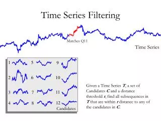
Project Recap • The algorithm: Nonlinear Diffusion use numeric solution with iterations to solve the diffusion equation • Why use it for image processing? • Image noise is smoothed • Edges remain sharp
Look at the hat (smoothed) Look at the edges (sharp!) dt = 30 !!! one iteration
Part A overview • Difficulties with the algorithm: • Very complex design, makes real time almost impossible • Transpose entire image • Reverse order loop • huge memory bandwidth required • So why use this model ? • Good results even after a single iteration (Yoni & Zion needed at least 20 iterations => need for multiple FPGAs)
Part A overview • Exploring different architecture solutions in Matlab • Comparing “sub-frames” processing vs. entire frame processing • Fixed-point analysis of the algorithm in Matlab • Learning about memory resources: • Internal memory: MRAM, M4K, M512 • External memory: DDR • Analyzing the memory bandwidth requirements of the algorithm • DVI signal generators • Implementation of a real-time streaming of pixels through DDR double buffering: • DVI in=>DDR write=>DDR read =>DVI out
Part B • Transpose image implementation • First transpose (800x525 => 525x800) • Second transpose (525x800 => 800x525) • Each transpose implies synchronization between internal memories and external memories using dedicated controllers and FIFOs • Detection of frame first pixel • Needed because each transpose block should start operating only at the first pixel of a frame • Also needed because the pipeline of Sergey & Roman need to get a starting signal, when the first pixel of a frame enter the pipeline. • Implementation of frame rate convertors • Down rate convertor at the input (60 fps => 15 fps) • Up rate convertor at the output (15 fps => 60 fps) • CORRECT DVI Synchronization! • PLL fixed location at input and output pins. • Registered Input/output pins. • Fixed-point analysis of the algorithm in Quartus
Part A Implementation DVI OUT DVI IN data data 24bit (RGB) 24bit DVI sync DVI sync Reset detector DVI Ctrl signals generator 3bit 3bit Internal memories Internal memories DVI clk PLL DVI clk 25.2MHz StratixII ¼ DVI clk Gidel’s memory controller DDR 2 banks 180MHz 180MHz
The Final architecture (PART B) DVI OUT lines DVI IN ¼ DVI clk data data T’ Freq controller: 4F to F Freq Controller+T’ 4F to F PIPE 24bit (RGB) 24bit columns DVI sync DVI sync T’ ¼ DVI clk PIPE Reset detector DVI Ctrl signals generator 3bit 3bit DVI clk PLL DVI clk 25.2MHz StratixII ¼ DVI clk Gidel’s memory controller DDR 2 banks 180MHz 180MHz
The Final architecture (PART B) DVI OUT lines DVI IN ¼ DVI clk data data T’ Freq controller: 4F to F Freq Controller+T’ 4F to F PIPE 24bit (RGB) 24bit columns DVI sync DVI sync T’ ¼ DVI clk PIPE Reset detector DVI Ctrl signals generator 3bit 3bit DVI clk PLL DVI clk 25.2MHz StratixII ¼ DVI clk Gidel’s memory controller DDR 8 Double Buffers 180MHz 180MHz
Fundamental DDR controller DVI OUT lines DVI IN ¼ DVI clk data data T’ Freq controller: 4F to F Freq Controller+T’ 4F to F PIPE 24bit (RGB) 24bit columns DVI sync DVI sync T’ ¼ DVI clk PIPE Reset detector DVI Ctrl signals generator 3bit 3bit DVI clk PLL DVI clk 25.2MHz StratixII ¼ DVI clk Gidel’s memory controller DDR 8 Double Buffers 180MHz 180MHz
Fundamental DDR controller • There are 4 bidirectional communication channels to/from DDR • Each channel requires another controller which is a variation of a fundamental controller • Up rate • Down rate • First tranpose (800x525 => 525x800) • Second Transpose (525x800 => 800x525) • Each one has asymmetric behavior for read and write
Fundamental DDR controller WRITE controller READ controller Synchronization states
DDR double buffer DDR WR controller DDR RD controller Dual Clock FIFO Dual Clock FIFO Pipe wr fin Pipe continue rd fin continue When finishing a frame: Each controller calculates its new address and waits for the other controller to finish. While waiting, the controller keeps sending “continue” signal to the other controller.
Bloody signals Flush -According to Gidel’s manual: flush signal is used to force writing the data to the memory when the last word is incomplete. BUT,even when using a port size equal to the memory width, one must use the ‘flush’ signal. Write empty: When performing write bursts from different addresses, one must wait for signal write_empty before starting a new burst. Without waiting - the data is lost. NOT in Gidel’s manual!
Down rate DDR controllers DVI OUT lines DVI IN ¼ DVI clk data data T’ Freq controller: 4F to F Freq Controller+T’ 4F to F PIPE 24bit (RGB) 24bit columns DVI sync DVI sync T’ ¼ DVI clk PIPE Reset detector DVI Ctrl signals generator 3bit 3bit DVI clk PLL DVI clk 25.2MHz StratixII ¼ DVI clk Gidel’s memory controller DDR 8 Double Buffers 180MHz 180MHz
Down rate controllers • Write controller: • Writes to DDR only one frame out of every 4 frames. • Frame rate: 15 frames/sec, pixel rate: 6.2MHz • Data loss is almost unnoticeable • Algorithm performance is not affected! • Actual bandwidth: 25 MHz (DVI clock) • Read controller: • Same as the fundamental DDR controller (burst of entire frame) • Actual bandwidth: 6.2 MHz
Down rate controllers WRITE controller “normal” READ controller Write 1 frame to DDR Counts 3 more frames, cleans the pipe
Up rate DDR controllers DVI OUT lines DVI IN ¼ DVI clk data data T’ Freq controller: 4F to F Freq Controller+T’ 4F to F PIPE 24bit (RGB) 24bit columns DVI sync DVI sync T’ ¼ DVI clk PIPE Reset detector DVI Ctrl signals generator 3bit 3bit DVI clk PLL DVI clk 25.2MHz StratixII ¼ DVI clk Gidel’s memory controller DDR 8 Double Buffers 180MHz 180MHz
UP rate controllers • Write controller: • Same as the fundamental DDR controller (burst of entire frame) • Actual bandwidth: 6.2 MHz • Read controller: • Reads the same frame from the DDR 4 times • To meet DVI data rate requirements • Actual bandwidth: 25MHz
Up rate controllers READ controller WRITE controller Sync with WR, swap addresses Main “loop”- reads 4 times the same frame
Transpose DDR controller DVI OUT lines DVI IN ¼ DVI clk data data T’ Freq controller: 4F to F Freq Controller+T’ 4F to F PIPE 24bit (RGB) 24bit columns DVI sync DVI sync T’ ¼ DVI clk PIPE Reset detector DVI Ctrl signals generator 3bit 3bit DVI clk PLL DVI clk 25.2MHz StratixII ¼ DVI clk Gidel’s memory controller DDR 8 Double Buffers 180MHz 180MHz
Transpose DDRII T’ WRITE DDRII T’ READ stratixII M-RAM WRITE M-RAM READ Sequential read from DDR Penalty every row skip Penalty all the time ! A reminder of how it works:
Transpose challenges • Two different transposes: • The first transpose - 800x525 • Transpose back - 525x800 • Debugging difficulty… • Synchronization to the beginning of the frame is required • Transpose counters: • “heavy” sequential Combinational logic causes Timing problems • Transpose on read or on write?
Transpose - memory configuration settings • Mram • Max number of rows (minimum penalty) • Number must divide 800 or 525 (no reminder) • Number must agree with Gidel controller • We chose 50 and 35 lines respectively • DDR • Loadbalancing • Gidel requirements
Transpose’s synchronization blocks Mram delaying the data Beginning of frame detection unit Write and read Address counters 3 Mrams for RGB
Transpose’s synchronization blocks DDR • Synchronization • on the WR controller: • New “Data in” port • designated states to deal with the first pixel of the frame after reset. • “cleans” the DCFIFO until detecting the first pixel of a new frame. • The WR controller sends reset signal to the RD controller.
Transpose counters • If (a) then • If (b) then • If (c) then • If (a) and (not b) and (not c) then • If (a) and (b) and (not c) then • If (a) and (b) and (c) then No code reuse and more HW (but we have enough!) guarantees shorter, parallel CL Long CL paths results in timing problems! • DDR and Mram counters: • The “heaviest” combinational logic of the entire design
Debugging difficulties First T’ Second T’ DDR Mram DDR Mram Dual clk FIFO Dual clk FIFO Addresses counters Addresses counters Addresses counters Addresses counters sync sync sync sync • Can’t easily “divide and conquer”- • Result is available only after 2 transposes: • We used SignalTap and built verification units
Debugging difficulties • Can’t simulate DDR’s behavior in MODELSIM • We don’t have a reliable model of the external memory’s behavior • Gidel’s controller is NOT “transparent” to the users - We know nothing about: • Gidel’s Internal implementation • Gidel’s handling requests policy of the DDR • We can read from the DDR through PCI but – it changes the data path…
Transpose on read • Read and Write protocols are different • WRITE: • Wait 16clks after start • Wait ~100 clks after flush • Wait for signal write_empty • READ: • Wait for signal almost_empty_RD • Looks like READ loop is shorter! • We successfully implemented transpose on read. • However, the improvement is not good enough to avoid using down/up rate controllers. • The combined up rate and transpose: read loop is more “busy”, better perform T’ on write!
Can we avoid the loss of data? 2 iterations: • Only 2 transposes are needed! • 2 FPGAs • DDR configuration (for each FPGA): • 1 transpose on bank A (19 MHz) • 1 transpose on bank B (19 MHz) For each bank: 180x0.75/3=45 >25.2 !!! Add more memory: • 1 T’ on bank A, 1 on bank B, 1 on additional memory: For each bank: 180x0.75/3=45 >25.2 !!!
Timing Problems DVI OUT lines DVI IN ¼ DVI clk data data T’ Freq controller: 4F to F Freq Controller+T’ 4F to F PIPE 24bit (RGB) 24bit columns DVI sync DVI sync T’ ¼ DVI clk PIPE Reset detector DVI Ctrl signals generator 3bit 3bit DVI clk PLL DVI clk 25.2MHz StratixII ¼ DVI clk Gidel’s memory controller DDR 8 Double Buffers 180MHz 180MHz
Timing Problems • Problems • Inconsistent compilation results • Jittery image • Lost data • Timing problems • Solutions • Registered I/Os • PLL Fixed placing
Additional Issues • Multiport • Data loss at end of burst • Long penalties • I/O strength • ProcII vs. ProcIII (no DVI) • Sync • Waiting for signal from second group
Additional Issues • SignalTap
Summery • Internal memory blocks: • Addressing controller • Transpose • Line reverse • External memory: • Double buffer on DDR • Up/down rate controller • DVI synchronization
We invite you to join us in the lab for a short demonstration