Understanding UML Class and Sequence Diagrams for Effective Software Design
This presentation introduces the principles of UML (Unified Modeling Language) focusing on Class and Sequence Diagrams. It addresses how to specify the structure and behavior of software systems during the design phase, transitioning from requirements to executable implementations. Attendees will learn how to depict system components, their attributes, methods, and associations. Key topics include class attributes, operations, relationship types (inheritance, association, etc.), and sequence diagram elements like participants and messages. A brief overview of UML tools like Violet, Rational Rose, and Visual Paradigm will also be provided.

Understanding UML Class and Sequence Diagrams for Effective Software Design
E N D
Presentation Transcript
CSE 403 Spring 2012 UML Class and Sequence Diagrams Violet Anton Osobov Slides adapted from Marty Stepp, CSE 403, Winter 2012
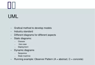
Design Phase • design: Specifying the structure of how a software system will be written and function (without actually writing the code). • a transition from "what" the system must do, to "how" the system will do it • What classes will we need in order to implement a system that meets our requirements? • What fields and methods will each class have? • How will the classes interact with each other?
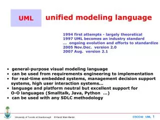
Introduction to UML • Unified Modeling Language (UML): depicts an OO system • programming languages are not abstract enough for OO design • UML is an open standard; lots of companies use it • many programmers either know UML or a "UML-like" variant
UML Class Diagrams • UML class diagram: A picture of the classes in an OO system, their fields and methods, and connections between the classes that interact or inherit from each other • What are some things not represented in a class diagram? • details of how the classes interact • algorithmic details; how particular behavior is implemented • trivial methods (get/set) • classes that come from libraries (ArrayList, etc.)
Diagram of a class • class name in top of box • write <<interface>> on top of interface’s names • use italics for an abstract class name • attributes • include all fields of the object • include properties “derived” properties • operations (constructors/methods) • may omit trivial methods – get/set • except from an interface • should not include inherited methods
Class attributes • syntax: • visibility name : type [count] = defaultValue • underline static attributes
Class operations/methods • syntax: • visibility name(parameters): returnType • underline static methods • parameter types listed as (name: type) • omit returnType on constructors andwhen return is void
Relationships between classes • generalization: an inheritance relationship • inheritance between classes • interface implementation • association: a usage relationship • dependency • aggregation • composition
Generalization • hierarchies are drawn top down • arrow from child to parent • trivial/obvious relationships often not drawn • Java: Object
Association • multiplicity • name • what relationship the objects have • navigability • direction
Engine Car 1 aggregation 1 composition 1 Book * dependency Page LotteryTicket Random Association types • aggregation: “is part of” • clear, white diamond • composition: “is entirely made of” • stronger version of aggregation • the parts only exist while the whole exists • black diamond • dependency: “uses temporarily” • dotted arrow or line
UML Sequence Diagrams • sequence diagram: an “interaction diagram” that models a single scenario executing in the system • UML representation of a use case
Sequence diagram key parts • participant: object or entity that acts in the diagram • message: communication between participants • axes in a sequence diagrams • horizontal: which participant/object is acting • vertical: time (down = forward in time)
Representing objects • Rectangles with object type, optionally preceded by “name : ” • Write object’s name if it clarifies the diagram • Object’s “life line” represented by dashed vertical line
Messages between objects • messages (methods calls) represented by arrow to other object • method name and arguments written above the arrow
Messages continued • messages (methods calls) represented by arrow to other object • dashed arrow back indicates return • different arrows for normal and concurrent/asynchronous calls
Object lifetime • creation: arrow with “new” written above it • object created after start of scenario appears lower than the others • deletion: an X at bottom of object’s lifeline • more applicable to languages with manual memory management (C, C++)
Activation Nesting Method activiation • activation: thick box over object's life line; drawn when object's method is on the stack • either that object is running its code,or it is on the stack waiting for another object's method to finish • nest activations to indicate recursion
If statements and loops • frame: box around part of diagram to indicate if or loop • if -> (opt) [condition] • if/else -> (alt) [condition], separated by horizontal dashed line • loop -> (loop) [condition or items to loop over]
Linking sequence diagrams • If one diagram is too large or refers to another, indicate with: • a "ref" frame that names the other diagram • Or an unfinished arrow and comment,
Violet • Tool for creating UML diagrams • Free • Easy to learn/use • http://sourceforge.net/projects/violet/ • Other software: • Rational Rose • Visual Paradigm UML Suite • Microsoft Visio