Download
1 / 42
430 likes | 649 Vues
A new method for high productive pre measuring of ballast tracks . Andreas Sinning and Patrick Walke. [S-2265] . Content. Introduction Basics Classic methods for pre measuring New Method for pre measuring Workflow Field usage experience Outlook. << 2. Needs for public transport.

E N D
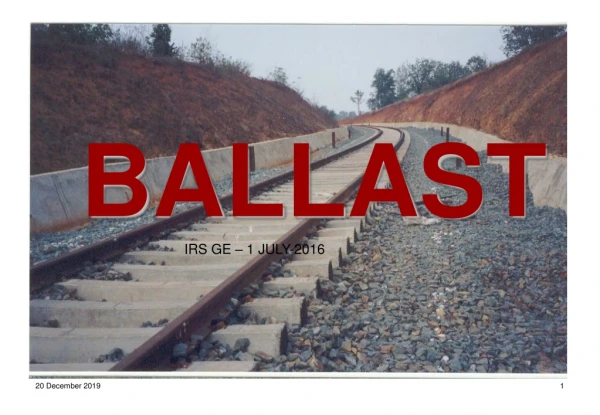
A new method for high productive pre measuring of ballast tracks Andreas Sinning and Patrick Walke [S-2265]
Content Introduction Basics Classic methods for pre measuring New Method for pre measuring Workflow Field usage experience Outlook <<2
Needs for public transport Increasing individual transport Full roads / Limited road capacity Demands on fast connections Competition with flight connections International connections E.g. EU / Russia Country development China Ecological way of transport Low emission <<3
Investments EU more than 150.000 km existing tracks 1/3 necessary to replace and increase the speed 125 Billion EUR Russia Connections to Moskau China 18.000 km new high speed lines before 2020 Maintenance for 100.000 km ballast tracks <<4
New Lines High Speed connections Slab Track Ballast Track • Renewal of existing tracks • Higher speed • New Alignment Track Construction tasks • Maintenance • Sleeper replacement • Rail replacement • Tamping <<5
Documentation Absolute track information • Planning • Design • GIS • Construction work • Provide data Surveying tasks • Acceptance inspection • Inner accuracy • Outer accuracy <<6
Surveying for ballast tracks Inner accuracy Camber Long and short chord measurements 30 m chord every 5 m <<7
Outer accuracy Reference coordinate system Independent reference system Bound to national system <<8
Alignment data Horizontal alignment Vertical alignment Superelevation Chainage line • Paper form 752.867200 2578004.315203 5633670.763793 157.13411000 1 62.953930 -30000.0000 -30000.0000 815.821130 2578043.624706 5633621.591049 157.00051761 0 80.000000 0.0000 0.0000 895.821130 2578093.643611 5633559.156209 157.00051761 1 62.962320 30004.0000 30004.0000 958.783450 2578132.958354 5633509.976912 157.13410999 0 425.069420 0.0000 0.0000 1383.852870 2578398.030462 5633177.680675 157.13410999 2 150.960890 0.0000 -2198.0000 • Digital form <<10
History Relative Chord measurement with chamber Relative and “Absolute” Chord measurement with reference to marking points Track marking plan Relative and Absolute Reference coordinate system Track marking plan or digital Alignment <<11
Classic pre measuring tools Mechanical chord Level and alignment instrument <<12
Classic pre measuring tools Tamping machine Using physical wire <<13
Classic pre measuring tools EM Sat Laser Alignment Alignment Method is prescribed for lines for lines with a design speed > 160 km/h <<14
Classic pre measuring tools Geodetic trolley Instrument outside of the track Free station setup ~ 150 m in both directions Productivity can be increased by using two instruments <<15
Comparism <<16
Idea for a new method Demands Flexible No track blocking Digital data flow Good speed Can be operated by two persons Line based method <<17
New method Realization Using Geodetic tools Relative station setup Two trolleys Alignment method GEDO CE Vorsys <<18
Total station based alignment Chord measurement Height Side 82/04 camber 5m chord 82/02 <<19
Total station based alignment Local 3D transformation • Absolute reference • Designed line • Local coordinate system • As built line <<20
Total station based alignment Local 3D transformation • As built line • Absolute reference • Designed line • Local coordinate system <<21
Total station based alignment Local 3D transformation • Absolute reference • Designed line • Local coordinate system • As built line <<22
Total station based alignment Alignment method 82/10 82/12 <<23
Theory ↔ Practice by … Watch the system from a point of view of practical application!
What is “standard”? • Assigned Manpower! • Train blockings as long as you order • No spatial problems along the track • Purpose of work: just finalizing, don‘t think about the accuracy • Enough time for the project Money is of no importance!
Is this REAL LIFE??? NOT OURS !
Description of the workflow • Before the measurement – data management • Basic data needed • Track axis • Gradient • Fixpoints along the track including reference values Digital or Analogue
Description of the workflow • Before the measurement – data management • Case 1: Workflow by using digital data • Convert the axis data into the data type needed by using the software GEDOoffice • Fixpoints in a csv-file (kind of Excel respectively ASCII data type) • That’s it!
Description of the workflow • Before the measurement – data management • Case 2: Workflow by using analog data (track marking plan) • Manual input of numerical data belonging to the relaying track • Reference values of fixpoints • Camber • Data of superelevation • Gradient data • Input by using the software VorsysCE Duration of data input: Analogue: 1 hour / 1 kilometer (= 0.6 miles) Digital: 5 minutes / 100 kilometer and more → NO track-blockings before the measurement!
Description of the workflow • During the measurement • Calibration of the trolley • Parameters of the trolley • Using the flexibility of the system • Starting the software VorsysCE - Starting a project • Starting the radio link
Description of the workflow • During the measurement • Description of the procedure of measurement • Perfect interaction of Trimble S6 and GedoCE vorsys • Definition of the chord • Measurement of the actual track set based on the camber • Constraints / Discontinuities • Decisive constraint: the platform
Description of the workflow • After the measurement - data interpretation • Data transfer • Description of the software GEDOTamp • Calculating the new trackline • Considering of guidelines, tamping pass, constraints
Description of the workflow • After the measurement - data interpretation • Convert to the ALC-Format (5-m-grid) • Handover of data to the tamping machine → start tamping immediately!
Alternatives of using the system • Other possibilities to fix the track geometry • Documentation of the track set after reaching the target position (2nd stabilisation) • Comparison of actual and theoretical track set • Marking out geometry main points • Proof of the gage
Future prospects… • Including GPS-Data • Documentation of the actual track set in plane and height without any axis data • Track monitoring
THIS is our “standard” ! Conclusion • Manpower only as much as needed! • Avoidance of train-blockings • No extra space needed…only the gage! • Data interpretation directly on site • Accurate and fast Optimal cost-benefit-factor
GedoCE Vorsys – A new method forhigh productive pre measuring
Thank you for your interest… Any Questions? Fragen? Des questions? a.sinning@sinning.depatrick.walke@ibh-vermessung.de
SinningVermessungsbedarf GmbHKorbacher Str. 15D-97353 WiesentheidTel.: +49 (0)9383 – 9732 – 0Fax: +49 (0)9383 – 9732 – 10www.sinning.de << IBH - Ingenieurbüro Herzbruch GmbHWilhelmstr. 43D-58332 SchwelmTel.: +49 (0)2336 – 4099 – 0 Fax: +49 (0)2336 – 4099 – 20www.ibh-vermessung.de a.sinning@sinning.depatrick.walke@ibh-vermessung.de <<42