Download

1 / 26
260 likes | 423 Vues
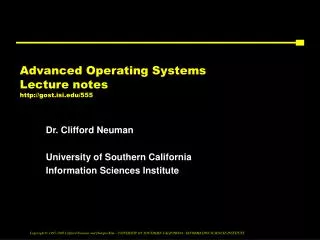
Lecture 4: Introduction to Advanced Pipelining. L.N. Bhuyan CS 162. Pipelined Processor: Datapath + Control. PCSrc. I. D. /. E. X. 0. M. W. B. u. E. X. /. M. E. M. x. 1. C. o. n. t. r. o. l. M. W. B. M. E. M. /. W. B. E. X. M. W. B. I. F. /. I. D.

E N D
Lecture 4: Introduction to Advanced Pipelining L.N. Bhuyan CS 162
Pipelined Processor: Datapath + Control PCSrc I D / E X 0 M W B u E X / M E M x 1 C o n t r o l M W B M E M / W B E X M W B I F / I D A d d A d d 4 A d d r e s u l t Branch RegWrite S h i f t l e f t 2 ALUSrc MemWrite MemToReg n R e a d o i r e g i s t e r 1 t P C A d d r e s s R e a d c u r d a t a 1 t R e a d s n Z e r o r e g i s t e r 2 I A L U R e a d A L U Imem 0 R e a d W r i t e d a t a 2 r e s u l t A d d r e s s 1 d a t a r e g i s t e r M M Regs u u W r i t e x x d a t a Dmem 1 0 W r i t e d a t a I n s t r u c t i o n 1 6 3 2 6 [ 1 5 – 0 ] MemRead S i g n A L U e x t e n d c o n t r o l I n s t r u c t i o n [ 0 1 6 ] 2 – ALUOp 0 M u I n s t r u c t i o n x [ 1 5 – 1 1 ] 1 RegDst
Four Branch Hazard Alternatives(Drawn in subsequent slides) #1:Stall until branch direction is clear – 3 slots delay –Well,move decision to 2nd stage by testing register – Save 2 cycles – See Fig. 6.51 #2:Predict Branch Not Taken • Execute successor instructions in sequence • “Squash” instructions in pipeline if branch actually taken • 47% branches not taken on average • PC+4 already calculated, so use it to get next instruction #3: Predict Branch Taken • 53% branches taken on average • But haven’t calculated branch target address • Move the branch adder to 2nd stage • Still incurs 1 cycle branch penalty – Why? #4 Dynamic Branch Prediction – Keep a history of branches and predict accordingly – 90% accuracy – employed in most CPUs
Reducing Stalls • Stall: wait until decision is clear • To stall pipeline, clear the contents of the existing instructions in the pipeline – clear contents of IF/ID, ID/EX and EX/MEM registers. • Move up decision to 2nd stage by adding hardware to check registers as being read – Adopted by many MIPS processors - See Fig. 6.51 – Penalty 1 cycle • Use Exclusive OR to compare the output of registers in the 2nd stage and enable the branch condition instead of waiting for comparison by the ALU in the 3rd stage. • Flush instruction in the IF stage by adding a control line called IF.Flush in Fig. 6.51 that zeros the IF/ID pipeline register – no operation.
IM ALU IM ALU ALU Control Hazard Solutions I n s t r. O r d e r Time (clock cycles) • guess branch taken, then back up if wrong: “branch prediction” • For example, Predict not taken • Impact: 1 clock per branch instruction if right, 2 if wrong (static: right ~ 50% of time) • More dynamic scheme: keep history of the branch instruction (~ 90%) DM Reg Reg add DM Reg Reg beq Load IM DM Reg Reg
IM ALU IM ALU ALU ALU Compiler Solutions I n s t r. O r d e r Time (clock cycles) • Redefine branch behavior (takes place after next instruction) “delayed branch” • Impact: 1 clock cycle per branch instruction if can find instruction to put in the “delay slot” ( 50% of time) DM Reg Reg add DM Reg Reg beq Misc IM DM Reg Reg Load IM DM Reg Reg
Delayed Branch add M1 ,M2,M3 sub M4, M5,M6 beq M1, M4, Exit or M8, M9 ,M10 xor M10, M1,M11 Exit: Example Nondelayed vs. Delayed Branch Nondelayed Branch or M8, M9 ,M10 add M1 ,M2,M3 sub M4, M5,M6 beq M1, M4, Exit xor M10, M1,M11 Exit:
Delayed Branch • Where to get instructions to fill branch delay slot? • Before branch instruction • From the target address: only valuable when branch taken • From fall through: only valuable when branch not taken • Compiler effectiveness for single branch delay slot: • Fills about 60% of branch delay slots • About 80% of instructions executed in branch delay slots useful in computation • About 50% (60% x 80%) of slots usefully filled See Fig. 6.54 pp. 503 from text
Dynamic Branch Prediction • Performance = ƒ(accuracy, cost of mis-prediction) • Branch History Table is simplest • Lower bits of PC address index table of 1-bit values • Says whether or not branch taken last time • No address check • Problem: in a loop, 1-bit BHT will cause two mispredictions: • End of loop case, when it exits instead of looping as before • First time through loop on next time through code, when it predicts exit instead of looping
Dynamic Branch Prediction • Solution: 2-bit scheme where change prediction only if get misprediction twice: • Red: stop, not taken • Green: go, taken Most widely adapted technique. Ex: Pentium T NT Predict Taken Predict Taken 11 10 T T NT NT Predict Not Taken 00 Predict Not Taken 01 T NT Implementation: A 2-bit counter is incremented when the branch is taken and is decremented when it is not taken. Condition: Incrementing 11 is 11 and decrementing 00 is 00.
BHT Accuracy • Mispredict because either: • Wrong guess for that branch • Got branch history of wrong branch when index the table because a wrong branch instn with same lsb address happens to be there in the BTB • 4096 entry table programs vary from 1% misprediction (nasa7, tomcatv) to 18% (eqntott), with spice at 9% and gcc at 12% • 4096 about as good as infinite table(in Alpha 21164). No further improvement is possible because the misprediction is due to program behavior not branch address conflict
Need Address at Same Time as Prediction • Branch Target Buffer (BTB): Address of branch index to get prediction AND branch address (if taken) • Note: must check for branch match now, since can’t use wrong branch address Branch Prediction: Taken or not Taken Predicted PC
Correlating Branches(Two-level branch Predictor) • Hypothesis: recent branches are correlated; that is, behavior of recently executed other branchesaffects prediction of current branch • Idea: record m most recently other executed branches as taken or not taken, and use that pattern to select the proper branch history table for this one • In general, (m,n) predictor means record last m other branches to select from 2m branch predictions each with n-bit counters • Old 2-bit BHT is then a (0,2) predictor because no other branch is considered
Correlating Branches (2,2) predictor • Then behavior of recent branches selects between, say, four predictions of next branch, updating just that prediction • Branch address 2-bits per branch predictors Prediction 2-bit global branch history
Dynamic Branch Prediction Summary • Branch History Table: 2 bits for loop accuracy • Correlation: Recently executed branches correlated with next branch • Branch Target Buffer: include branch address & prediction • Predicated Execution can reduce number of branches, number of mispredicted branches
Review: Summary of Pipelining Basics • Hazards limit performance • Structural: need more HW resources • Data: need forwarding, compiler scheduling • Control: early evaluation & PC, delayed branch, prediction • Increasing length of pipe increases impact of hazards; pipelining helps instruction bandwidth, not latency • Interrupts, Instruction Set, FP makes pipelining harder • Compilers reduce cost of data and control hazards • Load delay slots • Branch delay slots • Branch prediction • Today: Longer pipelines (R4000) => Better branch prediction, more instruction parallelism?
Case Study: MIPS R4000 (200 MHz) • 8 Stage Pipeline: • IF–first half of fetching of instruction; PC selection happens here as well as initiation of instruction cache access. • IS–second half of access to instruction cache. • RF–instruction decode and register fetch, hazard checking and also instruction cache hit detection. • EX–execution, which includes effective address calculation, ALU operation, and branch target computation and condition evaluation. • DF–data fetch, first half of access to data cache. • DS–second half of access to data cache. • TC–tag check, determine whether the data cache access hit. • WB–write back for loads and register-register operations. • 8 Stages: What is impact on Load delay? Branch delay? Why?
Case Study: MIPS R4000 IF IS IF RF IS IF EX RF IS IF DF EX RF IS IF DS DF EX RF IS IF TC DS DF EX RF IS IF WB TC DS DF EX RF IS IF TWO Cycle Load Latency IF IS IF RF IS IF EX RF IS IF DF EX RF IS IF DS DF EX RF IS IF TC DS DF EX RF IS IF WB TC DS DF EX RF IS IF THREE Cycle Branch Latency (conditions evaluated during EX phase) Delay slot plus two stalls Branch likely cancels delay slot if not taken
Arithmetic Pipeline • The floating point executions cannot be performed in one cycle during the EX stage. Allowing much more time will increase the pipeline cycle time or subsequent instructions have to be stalled • Solution is to break the FP EX stage to several stages whose delay can match the cycle time of the instruction pipeline • Such a FP or arithmetic pipeline does not reduce latency, but can decouple from the integer unit and increase throughput for a sequence of FP instructions • What is a vector instruction and or a vector computer?
MIPS R4000 Floating Point • FP Adder, FP Multiplier, FP Divider • Last step of FP Multiplier/Divider uses FP Adder HW • 8 kinds of stages in FP units: Stage Functional unit Description A FP adder Mantissa ADD stage D FP divider Divide pipeline stage E FP multiplier Exception test stage M FP multiplier First stage of multiplier N FP multiplier Second stage of multiplier R FP adder Rounding stage S FP adder Operand shift stage U Unpack FP numbers
MIPS FP Pipe Stages FP Instr 1 2 3 4 5 6 7 8 … Add, Subtract U S+A A+R R+S Multiply U E+M M M M N N+A R Divide U A R D28 … D+A D+R, D+R, D+A, D+R, A, R Square root U E (A+R)108 … A R Negate U S Absolute value U S FP compare U A R Stages: M First stage of multiplier N Second stage of multiplier R Rounding stage S Operand shift stage U Unpack FP numbers • A Mantissa ADD stage • D Divide pipeline stage • E Exception test stage
Pipeline with Floating point operations • Example of FP pipeline integrated with the instruction pipeline: Fig. A.31, A.32 and A.33 distributed in the class • The FP pipeline consists of one integer unit with 1 stage, one FP/integer multiply unit with 7 stages, one FP adder with 4 stages, and a FP/integer divider with 24 stages • A.31 shows the pipeline, A.32 shows execution of independent instns, and A.33 shows effect of data dependency • Impact of data dependency is severe. Possibility of out-of-order execution => creates different hazards to be considered later
R4000 Performance • Not ideal CPI of 1: • Load stalls (1 or 2 clock cycles) • Branch stalls (2 cycles + unfilled slots) • FP result stalls: RAW data hazard (latency) • FP structural stalls: Not enough FP hardware (parallelism)
FP Loop: Where are the Hazards? Loop: LD F0,0(R1) ;F0=vector element ADDD F4,F0,F2 ;add scalar from F2 SD 0(R1),F4 ;store result SUBI R1,R1,8 ;decrement pointer 8B (DW) BNEZ R1,Loop ;branch R1!=zero NOP ;delayed branch slot Instruction Instruction Latency inproducing result using result clock cycles FP ALU op Another FP ALU op 3 FP ALU op Store double 2 Load double FP ALU op 1 Load double Store double 0 Integer op Integer op 0 • Where are the stalls?
FP Loop Showing Stalls 1 Loop: LD F0,0(R1) ;F0=vector element 2 stall 3 ADDD F4,F0,F2 ;add scalar in F2 4 stall 5 stall 6 SD 0(R1),F4 ;store result 7 SUBI R1,R1,8 ;decrement pointer 8B (DW) 8 BNEZ R1,Loop ;branch R1!=zero 9 stall ;delayed branch slot • 9 clocks: Rewrite code to minimize stalls? Instruction Instruction Latency inproducing result using result clock cycles FP ALU op Another FP ALU op 3 FP ALU op Store double 2 Load double FP ALU op 1