Programmable Keyboard/Display Interface - 8279
Programmable Keyboard/Display Interface - 8279. 8279 contains the following features:. Simultaneous and independent scanning of a keyboard and refresh of a display, significantly offloading these functions from the microprocessor. Keyboard section: 8-character Keyboard FIFO


Programmable Keyboard/Display Interface - 8279
E N D
Presentation Transcript
8279 contains the following features: • Simultaneous and independent scanning of a keyboard and refresh of a display, • significantly offloading these functions from the microprocessor. Keyboard section: • 8-character Keyboard FIFO • 2-Key Lockout or N-key Rollover with Contact Debounce • Interrupt Output on Key Entry • Programmable Keyboard Scan & Debounce rates Display Section: • Dual 8- or 16-Numeric Display • Single 16-Character Display • Right or Left Entry 16-Byte Display RAM with address auto increment • Programmable display refresh rate Available in VHDL, Verilog, or FPGA-Specific Netlist
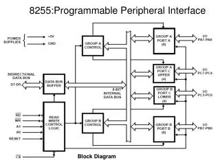
Pinout Definition 8279 • P A0: Selects data (0) or control/status (1) for reads and writes between micro and 8279. • P BD: Output that blanks the displays. • P CLK: Used internally for timing. Max is 3 MHz. • P CN/ST: Control/strobe, connected to the control key on the keyboard. • P CS: Chip select that enables programming, reading the keyboard, etc. • P DB7-DB0: Consists of bidirectional pins that connect to data bus on micro. • P IRQ: Interrupt request, becomes 1 when a key is pressed, data is available. • P OUT A3-A0/B3-B0: Outputs that sends data to the most significant/least significant nibble of display. • P RD(WR): Connects to micro's IORC or RD signal, reads data/status registers. • P RESET: Connects to system RESET. • P RL7-RL0: Return lines are inputs used to sense key depression in the keyboard matrix. • P Shift: Shift connects to Shift key on keyboard. • P SL3-SL0: Scan line outputs scan both the keyboard and displays
KEYBOARD SECTION • Has eight lines: RL0 to RL7 + two additional lines: CNTL/STB; connected to 8 columns of the keyboard • 2 modes: • 2 key lockout: if two keys are pressed simultaneously only 1st key is recognized • N-key rollover: simultaneous keys are recognized and their codes are stored in internal buffer. • Keyboard section also includes 8X8 FIFO which further consists of eight registers that can store 8 keyboard entries.
SCAN SECTION • Has scan counter and four scan lines: SL0 to SL3 • These are decoded using 4X16 decoder • Further these 16 lines are connected to rows of matrix keyboard and digital drivers of multiplexed display
DISPLAY SECTION • Has 8 output lines divided into 2 groups A0 to A3 and B0 to B3 • These lines can be used as a group of 8 lines or 2 groups of 4 lines each in conjunction to scan lines for display • Display can be blanked by BD line • Includes 16X8 display RAM • MPU can read or write into these registers
MPU INTERFACE SECTION • Includes 8 bidir. Data lines (DB0-DB7), one Interrupt Request (IRQ) and six lines for interfacing, including buffer add line A0 • When A0 is high – control word • When A0 is low – signals are interrupted and they act as data lines • IRQ goes high whenever data entries are stored in FIFO