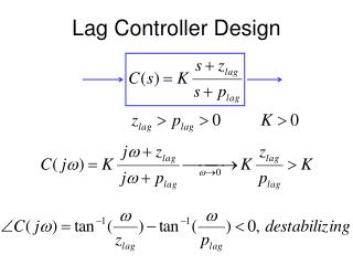
Keyboard Controller Design
Keyboard Controller Design. By Tamas Kasza. Presentation for. Digital System Design 2 (ECE 5572) Summer 2003. Content. Overview of design goals Available devices and software background PS2 Interface: PS2 interface controller keyboard codes on Seven Segment Display LCD Interface:

Keyboard Controller Design
E N D
Presentation Transcript
Keyboard Controller Design By Tamas Kasza Presentation for Digital System Design 2 (ECE 5572) Summer 2003
Content • Overview of design goals • Available devices and software background • PS2 Interface: • PS2 interface controller • keyboard codes on Seven Segment Display • LCD Interface: • Structure • Program modules, communicating state machines • Operation of the code itself - presentation • Summary
Design Goals Goals: • Attach a keyboard to the DIO2 device through PS/2 type of port; • Design a logic which can detect and display a pushed character on the LCD display of the I/O device; • Use VHDL during the development process.
Available Devices: D2 Board Digilab 2 (D2) FPGA-based development board with a 200K-gate Xilinx Spartan 2 XC2S200 FPGA in a PQ208 package that provides 143 user I/Os Attached parallel port cable for communication with the PC Attached AC/DC adaptor: 110 V (AC) 6 V (DC)
Available Devices: DIO 2 Digilab Digital I/O board 2 • 16x2 character LCD • Four seven segment displays • 16 LEDs in three colors • 8 switches • 15 pushbutton keypad • 8-bit VGA port • PS/2 port
Available Devices: Keyboard Keyboard with PS/2 port
Software Background • Xilinx ISE 5 Webpack • Project Navigator is the user interface that helps you manage the entire design process including design entry, simulation, synthesis, implementation and finally download the configuration of your FPGA or CPLD device
Software Background • iMPACT configuration tool allows you to configure your PLD designs using Boundary-Scan, Slave Serial, Select Map, and Desktop Configuration modes
PS/2 Interface • The DIO II Board receives two signals from the PS/2 interface: a clock signal and a serial data stream that is synchronized with the falling edges on the clock signal. • The clock and data signals (PS2C and PS2D) bypass the CPLD, and are connected directly to pins on the B connector.
PS/2 Port • Data signal uses 11-bit words that include a start, stop and odd parity bit
PS/2 Port • A PS2-style keyboard uses scan codes to communicate key press data (nearly all keyboards in use today are PS2 style). Each key has a single, unique scan code that is sent whenever the corresponding key is pressed. • If the key is pressed and held, the scan code will be sent repeatedly once every 100ms or so. When a key is released, a “F0” key-up code is sent, followed by the scan code of the released key.
PS/2 Port • Some keys, called extended keys, send an “E0” ahead of the scan code (and they may send more than one scan code), for example the ARROWS. When an extended key is released, a “E0 F0” key-up code is sent, followed by the scan code. • The keyboard should send data to the host only when both the data and clock lines are high (or idle). • The keyboard sends data to the host in 11-bit words that contain a ‘0’ start bit, followed by 8-bits of scan code (LSB first), followed by an odd parity bit and terminated with a ‘1’ stop bit. The keyboard generates 11 clock transitions (at around 20 - 30KHz) when the data is sent, and data is valid on the falling edge of the clock.
PS/2 Port – SHIFT detection • If a key has a “shift” character that is different than the non-shift character, the same scan code is sent whether the shift key is pressed or not, and the host device must determine which character to use.
PS/2 Port – Testing • VHDL module: ps2_control.vhd • Entity PS2_Control is • port( Clk : in std_logic; -- System Clock • Reset : in std_logic; -- System Reset • ps2clkin : in std_logic; -- Keyboard Clock Line • ps2datain : in std_logic; -- Keyboard Data Line • DoRead : in std_logic; -- From outside when reading the scan code • Scan_Err : out std_logic; -- To outside : Parity or Overflow error • Scan_DAV : out std_logic; -- To outside when a scan code has arrived • Scan_Code : out std_logic_vector(7 downto 0) -- Eight bits Data Out • ); • end PS2_Control;
PS/2 Port – Testing • Scan Code on Seven Segment Display
LCD Interface on DIO2 • The LCD display is a 16 character, 2 line display from the Okaya company (Okaya part number RC1602D). • The display uses a KS0066 Samsung controller that has: • a character-generator ROM (CGROM) containing 208 preset 5x8 character patterns, • a character-generator RAM (CGRAM) that can hold 8 user-defined 5x8 characters, and • a display data RAM (DDRAM) that can hold 80 character codes. • Writing a character code into a particular DDRAM location will cause the associated 5x8 character pattern to appear at the corresponding display location.
LCD Interface on DIO2 • The write-only Instruction Register (IR) is used to direct display operations (such as clear display, shift left or right, set DDRAM address, etc).
LCD Interface on DIO2 • A busy flag is available to indicate whether the display has competed the last requested operation; prior to initiating a new operation, the flag can be checked to see whether the previous operation has been completed. • The LCD display uses ASCII character codes: • Codes up through 7F are standard ASCII (which includes all “normal” alphanumeric characters). • Codes above 7F produce various international characters.
LCD Startup Sequence • The manufacturer requires that a startup sequence with specific timings be followed to ensure proper LCD operation.
Packages: • Lcdcntl_pkg.vhd: • Constants; • Timing definitions; • FSM type definitions for LCD STARTUP and ACCESS. • Lcdcommand_pkg.vhd • FSM type definitions: LCD COMMANDs and STATEs LCD Control in VHDL* • Implementation Constraints File: • PIN assignments: • General control purpose: 25; • PS/2-related: 2; NET "ps2clkin" LOC = "P31"; # P11=KCLK, A/E29 NET "ps2datain" LOC = "P30"; # P12=KDAT, A/E30 • LCD-related: 3: NET "lcd_e" LOC = "P36"; NET "lcd_rw_n" LOC = "P34"; NET "lcd_rs" LOC = "P33"; *Framework is based on Robert Villmow’s code
VHDL Modules • Top-level: ps2kbd.vhd: • General control, 50MHz clock input, 1MHz clock conversion; • State machine integrates ps2 port and LCD interface controls. • Instantiates: • Asciif, asciish: for Scan Code ASCII Code conversion. • Lcd: for LCD control; • Ps2_control: for ps2 port handling.
Part of ps2kbd.vhd’s central state machine: VHDL Modules – Cont. • DoRead <= '0'; -- Waiting for scan code • if Scan_DAV = '1' then • if shiftbit = '0' then ps2kbd <= AsciiOut; • else ps2kbd <= Asciishout; • end if; • -- LEFT SHIFT handling • if Code = "00010010" and release_bit = '0' then • shiftbit <= '1'; end if; • if release_bit = '1' and Code = "00010010" then • shiftbit <= '0'; end if; • -- Character release • if Code = "11110000" then release_bit <= '1'; • elsif release_bit = '0' and • (not (Code = "00010010")) -- no SHIFT • then • lcdcomm_ns <= IDLE; • testlcd_cs <= WAITINIT; • waitbusy <= '0'; • commandvalid <= '0'; • character_counter <= character_counter +1; • end if; • release_bit <= '0'; • end if;
VHDL Modules – Cont. • Asciif.vhd: Code Conversion (Asciish.vhd for SHIFTed characters) • entity asciif is • Port ( • Codein : in std_logic_vector(7 downto 0); • Asciiout : out std_logic_vector(7 downto 0)); • end asciif; • Lcd.vhd: containing files • Lcdcntl_top.vhd: General LCD Interface Control; • Lcd_init.vhd: initialization sequence; • Lcd_read_write.vhd: reading and writing a character. • Ps2_control: ps2 state machine
Results & Statistics HDL Synthesis ReportMacro Statistics # FSMs : 3 # Registers : 65 1-bit register : 55 10-bit register : 1 8-bit register : 6 3-bit register : 2 6-bit register : 1 # Counters : 4 11-bit up counter : 1 4-bit up counter : 2 2-bit up counter : 1 # Multiplexers : 7 2-to-1 multiplexer : 7 # Tristates : 3 7-bit tristate buffer : 1 8-bit tristate buffer : 2 # Adders/Subtractors : 2 10-bit adder : 1 6-bit adder : 1 # Comparators : 2 4-bit comparator greatequal : 1 4-bit comparator less : 1 # Xors : 1 1-bit xor2 : 1.
Summary • The VHDL program detects pushed characters and displays them in the first line of LCD display. • After 16 characters it clears the screen and sets the cursor back. • LEFT SHIFT function is also implemented for displaying: • Capital letters; • Special characters (for example !@#$%^&, etc.).
Comments • Digilent specifications are sometimes inaccurate and do not match with each other or other documents: • Scan code for Z is 1A and not 1Z as it is indicated in dio2_rm.pdf. • Okaya documentation for LCD is different to Digilents documents. • PS/2 port signals can be bidirectional in case of keyboard PS/2 port.