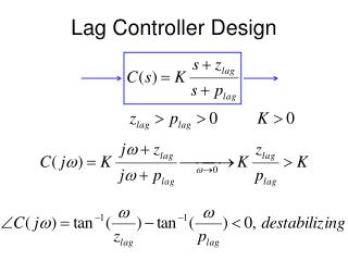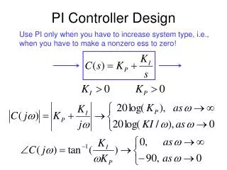
Overall controller design
This guide covers the design and implementation of advanced control systems, including PD, PI, and PID controllers. It outlines steps for drawing the root locus for G(s) and identifying desired regions for closed-loop poles based on specifications. Key aspects include selecting appropriate design parameters, computing angle deficiency, evaluating error constants, and analyzing step responses. The guide also addresses lead-lag designs, optimizing for overshoot and settling time, and highlights considerations for operational amplifier control circuits.

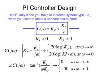
Overall controller design
E N D
Presentation Transcript
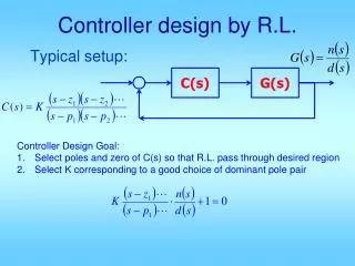
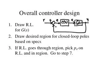
Overall controller design • Draw R.L.for G(s) • Draw desired region for closed-loop poles based on specs • If R.L. goes through region, pick pd on R.L. and in region. Go to step 7.
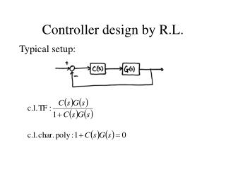
Pick pd in region (leave some safety flex) • Compute angle deficiency: • a. PD control, choose zpd such that then
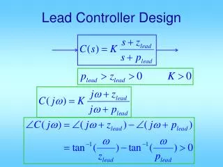
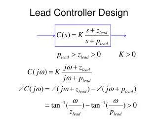
b. Lead control: choose zlead, plead such that You can select zlead & compute plead. Or you can use the “bisection” method to compute z and p. Then
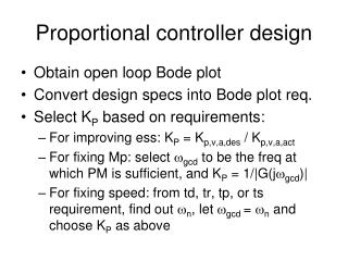
Compute overall gain: • If there is no steady-state error requirement, go to 14. • With K from 7, evaluate error constant. You already have:
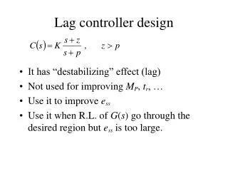
The 0, 1, 2 should matchp, v, a This is for lag control. For PI:
Compute desired error const. from specs: • For PI : set K*a = K*d & solve for ziFor lag : pick zlag & let
Re-compute K • Get closed-loop T.F. Do step response analysis. • If not satisfactory, go back to 3 and redesign.
Lead-lag design example Too much overshoot, too slow & ess to ramp is too large.
Clearly R.L. does not pass through desired region.need PD or lead. Let’s do lead.Pick pd in region
Now choose zlead & plead. Could use bisection. Let’s pick zlead to cancel plant pole s + 0.5
Use our formula to get plead Now compute K : Now evaluate error constant Kva
Should re-compute K, but let’s skip: do step response.
Op-amp controller circuit: • Proportional:
If R1C1 > R2C2then z < pThis is lead controller If R1C1 < R2C2then z > pThis is lag controller