Chapter 8: Main Memory
Chapter 8: Main Memory. Chapter 8: Memory Management. Background Swapping Contiguous Memory Allocation Segmentation Paging Structure of the Page Table Example The Intel 32 and 64-bit Architectures ARM Architecture. Objectives. To discuss various ways of organizing memory hardware


Chapter 8: Main Memory
E N D
Presentation Transcript
Chapter 8: Memory Management • Background • Swapping • Contiguous Memory Allocation • Segmentation • Paging • Structure of the Page Table • Example • The Intel 32 and 64-bit Architectures • ARM Architecture
Objectives • To discuss various ways of organizing memory hardware • To discuss various memory-management techniques • paging • segmentation • To discuss the Intel Pentium • segmentation • segmentation with paging
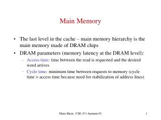
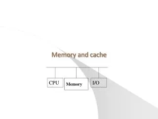
1. Background • Program must be run in memory • Protection of memory required to ensure correct operation • CPU can access directly • Main memory - take many cycles, causing a stall • Registers – in one CPU clock or less • Cache – between main memory and CPU registers • Inside memory unit, we can see a stream of • addresses + read requests, or • address + data and write requests
Base and Limit Registers • Define the logical address space • Every memory access • generated in user mode • checked by CPU • ensure between base and limit for that user
Address Binding • Programs are loaded into memory to run • It is inconvenient • to have first user process physical address always at 0000 • Address Binding • addresses represented in different ways at different stages of a program’s life • Source code addresses usually symbolic • Compiled code addresses bind to relocatable addresses • i.e. “14 bytes from beginning of this module” • Linker or loader will bind relocatable addresses to absolute addresses • i.e. 74014 • Each binding maps one address space to another
Binding of Code and Data to Memory • Three different stages • Compiling time • If memory location is known as a priori, absolute codecan be generated • must recompile code if starting location changes • Loading time • Must generate relocatable code if memory location is not known at compiling time • Execution time • Binding delayed until run time • if the process can be moved during its execution from one memory segment to another • Need hardware support for address maps • base and limit registers
Logical vs. Physical Address Space • Logical Address • generated by the CPU • also referred to as virtual address • Central to proper memory management • Logical address space • A set of all logical addresses generated by a program • Physical Address • Can be seen in memory unit • Same as LA compile and load time address-binding schemes • But differ in execution-time address-binding scheme • Physical address space • A set of all physical addresses generated by a program
Memory-Management Unit (MMU) • Hardware device • maps virtual to physical address at run time • Base register is called relocation register • A user program • Only deals with logical addresses • Never sees the real physical addresses • Binding occurs at execution-time when reference is made to location in memory • Logical address bound to physical address
Dynamic relocation • Using a relocation register • Routine is not loaded until it is called • Unused routine is never loaded • Better memory-space utilization • All routines are kept on disk in relocatable load format • No special support from the OS is required • Implemented through program design • OS can help by providing libraries to implement dynamic loading
Dynamic Linking • Static linking • system libraries and code combined by the loader into the binary program image • Dynamic linking • linking postponed until execution time • Stub • A small piece of code • Used to locate the appropriate memory-resident library routine • Stub replaces itself with the address of the routine, and executes the routine • OS checks if routine is in processes’ memory address • If not in address space, add to address space • Useful in system patching • Versioning may be needed
2. Swapping • To execute a large code program • A process can be swapped temporarily out of memory to a backing store, and • then brought back into memory for continued execution • Total physical memory space of processes can exceed physical memory • lower-priority process is swapped out so higher-priority process can be loaded and executed • Question? • Does the swapped out process need to swap back into the same physical addresses? • Depends on address binding method, and also • Consider pending I/O to / from process memory space • Modified versions swapping • Found on many systems (i.e., UNIX, Linux, and Windows) • Swapping normally disabled • Started if more than threshold amount of memory allocated • Disabled again once memory demand reduced below threshold
Context Switch Time including Swapping • Context switch time • Defined as the time between swap in and out • Could be very high • Example • 100MB process swapping to hard disk with transfer rate of 50MB/sec • Swap out time of 2000 ms • Plus swap in of same sized process • Total context switch swapping time can be 4000ms (4 seconds) • Other constraints • Pending I/O • can’t swap out as I/O would occur to wrong process • Or always transfer I/O to kernel space, then to I/O device • Known as double buffering, adds overhead
Swapping on Mobile Systems • Not typically supported • Flash memory based • Small amount of space • Limited number of write cycles • Poor throughput between flash memory and CPU on mobile platform • Instead other methods used to free memory if low • iOS • asks apps to voluntarily relinquish allocated memory • Read-only data thrown out and reloaded from flash if needed • Failure to free can result in termination • Support paging • Android • terminates apps if low free memory • but first writes application state to flash for fast restart • Support paging
3. Contiguous Allocation • Main memory usually into two partitions: • Resident OS, usually held in low memory with interrupt vector • User processes then held in high memory • Each process contained in single contiguous section of memory • Relocation registers • used to protect user processes • from each other, and • from changing operating-system code and data • Base register contains value of smallest physical address • Limit register contains range of logical addresses • each logical address must be less than the limit register • MMU maps logical address dynamically • Can then allow actions such as kernel code being transient and kernel changing size
Contiguous Allocation (Cont.) • Multiple-partition allocation • Degree of multiprogramming limited by number of partitions • Variable-partition sizes for efficiency (sized to a given process’ needs) • Hole • block of available memory • holes of various size are scattered throughout memory • When a process arrive • it is allocated memory from a hole large enough to accommodate it • Process exiting frees its partition, adjacent free partitions combined • OS maintains a) allocated partitions b) free partitions (hole) OS OS OS OS process 5 process 5 process 5 process 5 process 9 process 9 process 8 process 10 process 2 process 2 process 2 process 2
Dynamic Storage-Allocation Problem How to satisfy a request of size n from a list of free holes? • First-fit • Allocate the first hole that is big enough • Best-fit • Allocate the smallest hole that is big enough; • must search entire list, unless ordered by size • Produces the smallest leftover hole • Worst-fit • Allocate the largest hole; must also search entire list • Produces the largest leftover hole First-fit and best-fit better than worst-fit in terms of speed and storage utilization
Fragmentation • External Fragmentation • total memory space exists to satisfy a request, but it is not contiguous • Internal Fragmentation • allocated memory may be slightly larger than requested memory • this size difference is memory internal to a partition, but not being used • First fit analysis reveals • that given N blocks allocated, 0.5 N blocks lost to fragmentation • 1/3 may be unusable -> 50-percent rule
Fix Fragmentation • Reduce external fragmentation by compaction • Shuffle memory contents to place all free memory together in one large block • Compaction is possible only if relocation is dynamic, and • is done at execution time • I/O problem • Latch job in memory while it is involved in I/O • Do I/O only into OS buffers • Consider that backing store has same fragmentation problems
4. Segmentation • Memory-management scheme • supports user view of memory • A program is a collection of segments • A segment is a logical unit such as: • main program • procedure • Function • Method • Object • local variables, global variables • common block • Stack • symbol table • arrays
1 4 2 3 Logical View of Segmentation 1 2 3 4 user space physical memory space
Segmentation Architecture • Logical address consists of a two tuple: • <segment-number, offset>, • Segment table • maps two-dimensional physical addresses • each table entry has: • base– contains the starting physical address where the segments reside in memory • limit– specifies the length of the segment • Segment-table base register (STBR) • points to the segment table’s location in memory • Segment-table length register (STLR) • indicates number of segments used by a program • segment number s is legal if s < STLR
Protection from Segmentation • With each entry in segment table associate: • validation bit = 0 illegal segment • read/write/execute privileges • Protection bits associated with segment • code sharing occurs at segment level • Since segments vary in length • memory allocation is a dynamic storage-allocation problem
5. Paging • Frames • physical memory • fixed-sized block • power of 2, between 512 bytes and 16 Mbytes • Pages • logical memory • blocks of same size • Some Points • Physical address space of a process can be noncontiguous; • process is allocated physical memory whenever the latter is available • Avoids external fragmentation • Avoids problem of varying sized memory chunks • Keep track of all free frames • To run a program of size Npages, need to find N free frames and load program • Set up a page table to translate logical to physical addresses • Backing store likewise split into pages • Still have Internal fragmentation
Address Translation Scheme • Address generated by CPU is divided into: • Page number (p) • used as an index into a page table which contains base address of each page in physical memory • Page offset (d) • combined with base address to define the physical memory address that is sent to the memory unit • For given logical address space 2m and page size2n page offset page number p d m - n n
Paging Example n=2 and m=4 32-byte memory and 4-byte pages
Internal fragmentation & Paging • Calculating internal fragmentation • Page size = 2,048 bytes • Process size = 72,766 bytes • 35 pages + 1,086 bytes • Internal fragmentation of 2,048 - 1,086 = 962 bytes • Worst case fragmentation = 1 frame – 1 byte • On average fragmentation = 1 / 2 frame size • So small frame sizes desirable? • But each page table entry takes memory to track • Page sizes growing over time • Solaris supports two type of page sizes – 8 KB and 4 MB
Free Frames After allocation Before allocation
Implementation of Page Table • Page table is kept in main memory • Page-table base register (PTBR)points to the page table • Page-table length register (PTLR)indicates size of the page table • In this scheme every data/instruction access requires two memory accesses • One for the page table and one for the data / instruction • Two memory access problem can be solved by • TLB-Translation Look aside Buffers (fast-lookup hardware cache) • TLB • Some TLBs storeaddress-space identifiers (ASIDs)in each TLB entry • uniquely identifies each process to provide address-space protection for that process • Otherwise need to flush at every context switch • TLBs typically small (64 to 1,024 entries) • On a TLB miss, value is loaded into the TLB for faster access next time • Replacement policies must be considered • Some entries can be wired down for permanent fast access
Associative Memory • Associative memory – parallel search • Address translation (p, d) • If p is in associative register, get frame # out • Otherwise get frame # from page table in memory Page # Frame #
Effective Access Time • Associative Lookup = time unit • Can be < 10% of memory access time • Hit ratio = • Hit ratio • percentage of times that a page number is found in the associative registers; ratio related to number of associative registers • Consider = 80%, = 20ns for TLB search, ∆=100ns for memory access • Effective Access Time(EAT) EAT = ∆ * + 2*∆*(1 – ) • Consider = 80%, = 20ns for TLB search, 100ns for memory access • EAT = 0.80 x 100 + 0.20 x 200 = 120ns • Consider more realistic hit ratio -> = 99%, = 20ns for TLB search, 100ns for memory access • EAT = 0.99 x 100 + 0.01 x 200 = 101ns
Memory Protection • Memory protection is implemented • associating protection bit with each frame to indicate if read-only or read-write access is allowed • Can also add more bits to indicate page execute-only, and so on • Valid-invalidbit • attached to each entry in the page table • “valid” bit • indicates that the associated page is in the process’ logical address space, and is thus a legal page • “invalid” bit • indicates that the page is not in the process’ logical address space • Or use page-table length register (PTLR) • Any violations result in a trap to the kernel
Shared Pages • Shared code • One copy of read-only (reentrant) code is shared among processes • Similar to multiple threads sharing the same process space • Also useful for inter-process communication if sharing of read-write pages is allowed • Private code and data • Each process keeps a separate copy of the code and data • The pages for the private code and data can appear anywhere in the logical address space
6. Structure of the Page Table • Can be huge using straight-forward methods • Consider a 32-bit logical address space as on modern computers • Page size of 4 KB (212) • Page table would have 1 million entries (232 / 212) • If each entry is 4 bytes -> 4 MB of physical address space / memory for page table alone • That amount of memory used to cost a lot • Don’t want to allocate that contiguously in main memory • Hierarchical Paging • Hashed Page Tables • Inverted Page Tables
Hierarchical Page Tables • Break up the logical address space into multiple page tables • A simple technique is a two-level page table • then page the page table
Two-Level Paging Example • A logical address is divided into: • a page number consisting of 22 bits • a page offset consisting of 10 bits • Since the page table is paged • the page number is further divided into: • a 12-bit page number • a 10-bit page offset • Thus, a logical address is as follows: • where p1 is an index into the outer page table, • and p2 is the displacement within the page of the inner page table • Known as forward-mapped page table page number page offset p2 p1 d 12 10 10
64-bit Logical Address Space • Even two-level paging scheme not sufficient • If page size is 4 KB (212) • Then page table has 252 entries • If two level scheme, inner page tables could be 210 4-byte entries • Address would look like • Outer page table has 242 entries or 244 bytes • One solution is to add a 2nd outer page table • But in the following example the 2nd outer page table is still 234 bytes in size • And possibly 4 memory access to get to one physical memory location page offset outer page inner page p2 p1 d 42 10 12