Download
1 / 19
190 likes | 336 Vues
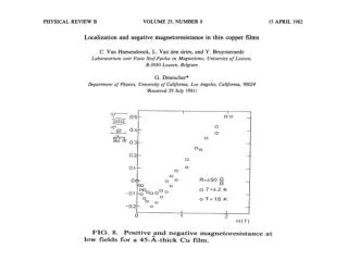
TEST BEAM A SLAC. close to shower maximum. shower nearly dissipated. 6 GHz bandwith oscilloscope. Antenna V/V rms. Antenna V/V rms. Time relative to beam entry. Time relative to beam entry. P.W. Gorham et al. TEST BEAM A SLAC. sensitive to cherenkov and transition radiation.

E N D
TEST BEAM A SLAC close to shower maximum shower nearly dissipated 6 GHz bandwith oscilloscope Antenna V/Vrms Antenna V/Vrms Time relative to beam entry Time relative to beam entry P.W. Gorham et al..
TEST BEAM A SLAC sensitive to cherenkov and transition radiation insensitive to cherenkov and transition radiation 7 ns decay constant, compatible with plasma cooling classical bremsstrahlung theory assuming coherence P.W. Gorham et al..
THE AMY OBJECTIVE Limitations of SLAC measurements It has been proved only the existence of a microwave emission • the absolute yield is not known precisely • --> this affect the uncertainty on the threshold in energy of • an air shower detector • the spectrum in frequency has not been measured • --> it may give important informations on the underlying process • --> if there are bright lines the signal/noise of a telescope can be improved • --> if not, satellite televisions band are preferable to keep low the costs With the AMY experiment we would like to overcome this limitations confirming and measuring precisely the absolute microwave yield and its frequency spectrum in the range between 1 and 25 GHz
The DAFNE Beam Test Facility e-/e+ In comparison to SLAC the BTF beam provides a larger shower equivalent energy
ANECHOIC FARADAY CHAMBER 2 antennas beam axis RF adsorber SATIMO AEP 12 attenuation 1GHz: 30 dB > 6 GHz: 50 dB 2 m 2 m 4 m copper 30 cm choice of dimensions • far field approximation (-> height and width) • entrance and exit walls outside the antenna field of view (-> length)
ANECHOIC FARADAY CHAMBER 2 antennas beam axis 2 m 2 m 4 m • spectrum analyzer -> frequency spectrum and absolute yield • power detector & FADC (*) ->time evolution of the signal (*) flexibility of a VME system (beam monitoring)
EXPECTED FLUX DENSITY at the maximum energy deposit within the chamber depends on the degree of coherence = 1÷2 assuming an alumina target observed track lenght beam-antenna distance alumina target alumina target
THE ANTENNA Rohde & Schwarz HL050 Log-periodic 0.85-26.5 GHz 27.4 cm
SPECTRUM MEASUREMENT Spectrum analyzer amplifier ANTENNA Rohde & Schwarz FSV30 9 KHz - 30 GHz 40 MHz bandwidth Gampl ≈ 25 dB
SPECTRUM MEASUREMENT Spectrum analyzer amplifier ANTENNA Expected signal at the maximum energy deposit quadratic scaling bandwidth amplifier antenna effective area linear scaling well above the expected instrumental noise (< -80 dBm)
TIME MEASUREMENT FADC power detector amplifier ANTENNA AD8317/8318 500 MS/s up to 10 GHz response time < 10 ns (no signal -10 dBm) 12 bit resolution 4 channels
TIME MEASUREMENT FADC power detector amplifier ANTENNA Constraints from power detector • difficult to go above 10 GHz • minimum signals > -60 dBm Measuring the exponential decay with a 30-40 dB dynamic range high amplification gain perform an initial measurement around a fixed frequency (commercial feeds in satellite bands) once the spectrum has been measured, study the time signal evolution in the bands we will find interesting (above 10 GHz we may use frequency down converters) C band
Cherenkov: no target - quadratic scaling density flux at the end of the camera after the adsorption (50 dB) density flux at the antenna cross-polarized (40 dB) MBR density flux at the antenna maximum shower development
For a realistic calculation: • time separation between electrons • coherence only if t << 1/f • (0.04 ns < 1/f < 1 ns) • 1 ns < bunch duration < 10 ns • only particles within the chamber contribute to the signal • modelling RF absorption
Dealing with 1010 particles Expected cherenkov signal in the spectrum analyzer in case of a copolarized antenna > -10 dBm An import goal of the test beam will be to measure the cherenkov radiation and to make a comparison with theoretical calculations
Agilent (?) Agilent (?) The experiment has been fully funded by INFN (~ 120 k€) and some of the instrumentation will be bought already during this year.