Download
1 / 25
250 likes | 268 Vues
Status of FTK. Paola Giannetti INFN Pisa for the FTK Group ATLAS Italia November 17, 2009. Status & Evolution. 10 34 WH(120) →lv bjet-bjet , Hqq → t jet- t jet qq, isolated leptons : DONE New architecture good performances on b-jets and t -jets

E N D
Status of FTK Paola Giannetti INFN Pisa for the FTK Group ATLAS Italia November 17, 2009
Status & Evolution • 1034 WH(120)→lv bjet-bjet, Hqq → tjet-tjet qq, isolated leptons: DONE • New architecture • good performances on b-jets and t-jets • new application: muon & electron isolation • 3 x1034 : to be DONE for end2009 • performance studies: ongoing • More powerful architecture: in evolution • After approval split into 2 activities • vertical slice @CERN (start 2011)→ protoFTK studies → insertion new prototypes → 1034 • build the system for 3 x1034(2015?)
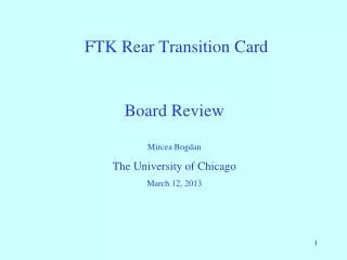
ATHENA full Simulation + FTKsim IP resolution WH 11 L 10**34 cm σFTK = σoffline⊕30μm RMS=87 m RMS= 72 m WH 10**34 pile-up IPAT FTK IPAT FTK 3x1034 as good as single m & 1034 FTK WH 3x1034 FTK single m Offline single m nPix+nSCT hits >=10 |d|<2.2 mm pT > 1 GeV chi2/dof < 4 RMS=69 m IPAT FTK IP resolution 3x1034
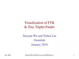
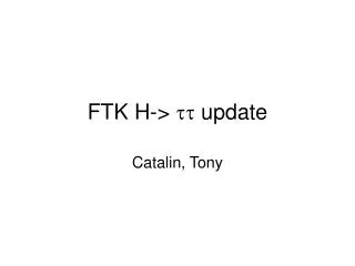
leading PT track RS RI RO iPat Tracks FTK Sim Tracks Jet axis t-jet efficiency rejection Single Prong (1,0) || < 0.8 for jet 1033 Lumi Efficiency vs. Efficiency vs. pT Fakes as a function of jet Fakes as a function of jet Pt 4
τ-tagging Performance (barrel-only) • 1-prong efficiency similar to using offline tracks for the same algorithm, with very low fake rate 1033 1033 1034 qqH(120)qqττ QCD jets qqH(120)qqττ 1-prong (1,0) FTK tracks iPat tracks 1033 • Good efficiency at 1033 & 1034 • 3-prong efficiencies are also similar 3-prong (3,0)
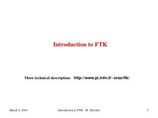
μ Trigger at High Luminosity track-based isolation with z0 of all tracks in the cone within 10mm of the muon track z0
Near-term Plans • Detailed analysis of 3x1034 samples • b, τ, μ, e performance with baseline algorithms • improved b, τ tagging performance with algorithms that make use of the freed-up L2 time • FTK timing (data flow) • Default L2 timing • Complete TDR (end of the year) • Be approved (beginning 2010) • ITALIAN Institutions (up to now): PISA – FRASCATI – BOLOGNA (vertical slice)- PAVIA (vertical slice)
FTK WH 3x1034 FTK single m Pt resolution FTK WH 3x1034 FTK single m ATHENA full Simulation + FTKsim
Feeding FTK @ 100kHz event rate Pixel barrel SCT barrel Pixel disks ATLAS Pixels + SCT Divide into f sectors 1/2f AM Allow a small overlap for full efficiency 1/2f AM 6 buses 40MHz/bus (to be increased) 11 Logical Layers: full h coverage • 8 f regions each with • 6 sub-regions (h-f towers) • df~25o, dh~1.7 • bandwidth for up to • 3*10E34 cm-2s-1 9
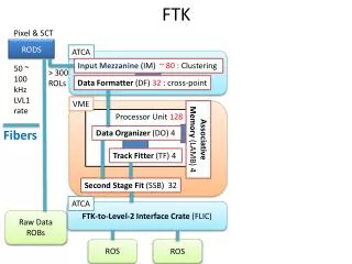
PIPELINEDAM+RW EVENT # 1 CHANGES FOR 1034 EVENT # N AM-board HITS DO-board SUPER BINS DATA ORGANIZER TRACK FITTER + HW cleaning ROADS ROADS + HITS 2nd step: track fitting Pixels & SCT cluster finding split by layer RODs overlap regions HITS AM brd AM brd Data Formatter (DF) 6x h-f towers NEW Data Organizer Data Organizer 50~100 KHz event rate … Track Fitter Track Fitter S-links Remove duplicate trks ~Offline quality Track parameters Raw data ROBs Track data ROB 10
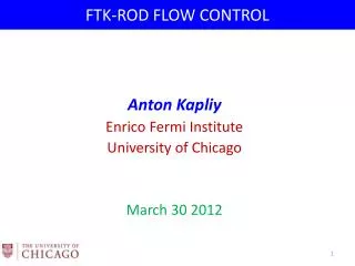
AM-B7-TSP AM-B8-TSP AM-B3-TSP AM-B4-TSP AM-B5-TSP AM-B0-TSP AM-B2-TSP AM-B6-TSP AM-B1-TSP RoadWarriors Hit-Warrior DO0 DO2 DO3 DO4 DO5 DO1 TrackFitter O(60x106 ) Patterns for 65 nm O(30x106 ) Patterns for 90 nm TSP DO TSP AMBoard+RW DO-TF AMBoard+RW TF DO FOR 11 LAYERS BUT ONLY ROADS IN 2 AMBOARDS TF TF TF New Crate Layout for 1034 OLD NEW X 6 = 12 AMBoard + 6 DO + 6 TF gruped like this= 3x6=18 slots Looks similar if look in front of it But on the back more cards! More dense boards! AUX board
BUT 3x1034 is horribly worse! • We have succeeded in running digitization at 3x1034 by turning off cavern background and reducing the range of bunch crossing for pile-up (still with the full range for tracking) • The number of silicon hits is large! • We are currently running these through FTK simulation • Huge number of roads (fired patterns) found → increase resolution
Number of fits is not any more a problem Heavily used 1 SCT layers alone are blind because of too large number of firing roads even at very high resolution 4 3 2 1 2 3 4 5 6 7 8 Possible Architectures- @ 3x1034 • Two pattern banks offset by ½ SS • Require road to be found in both. Reduced effective SS width decreases # of combinations w/ small (x2) increase in pattern bank size • Tree Search Processor (TSP) • Smaller SS binary search after AM. Reduces SS size fewer combinations • Split Architecture • First find SCT tracks, then fit with pixels (ala CDF SVT). Avoid 11L combinatorics by only taking good fits
New Organization inside the AMBoards: TSPs in the AUX board and below each LAMB to fight fakes gradually: 4 kroads from Lamb → 400x4 from AMboard→ ~300 from AUX LAMB Standard cell chip MINI DO+ TSP Connectors for LVDS Cables FIFOS Replaced By FPGA FPGA 40 MHz clock DRIVERS RECEIVERS LVDS AUX card AMBoard with TSP for each LAMB
The AM chip R&D to design the new full custom cell for patterns (M.Beretta Frascati, L.Sartori & E. Bossini Pisa). Copy the CAM structure. First small 90 nm prototype in 2010. We hope to gain between a factor 4 and 8 as pattern # (reduced size of the pattern) Possible collaboration with Fermilab to try the 3D technology. Not yet started. Trying to evaluate possible advantages. First attempt: 4 130 nm layers each one made exactly equal to the already existing CDF AM chip (1 cm2 large area): measure the yeld, the consumption…..
1 4 3 2 1 2 3 4 5 6 7 8 Binary search to go down to better SS resolutions FAT ROAD Found by AM (default SS for example or even larger) PARENT PATTERN Depth 0 Depth 1 PATTERN BLOCK Depth 2 THIN ROAD • Advantages: • pattern bank saved in dense RAMs • high degree of parallelism Algorithm: NIM A287 (1990) 436-438 http://www.pi.infn.it/~paola/Tree_search_algorithm.pdf Tree Search Processor: NIM A 287, 431 (1990), http://www.pi.infn.it/~orso/ftk/NIMA287_431.pdf IEEE Toronto, Canada, November 8-14 1998 http://www.pi.infn.it/~paola/TSP_v14.pdf
μ Trigger at High Luminosity • The default muon trigger uses calorimeter and tracking information, but the calorimeter is sensitive to pile-up • This is drastically improved with the use of tracking information: track-based isolation requiring that the z0 of all tracks in the cone is within 10mm of the muon (inner detector) track z0
Pattern Recognition • Massively parallel processing • A large bank of pre-computed hit patterns is used for very fast tracking (memory speed) SuperStrip (SS) • Linearized track fit using full-resolution silicon hits after pattern recognition Current chip used in CDF SVT: 0.18 μm standard cells, with 5000 patterns/chip. IEEE Trans.Nucl.Vol. pp 2428-2433
Track Fitting Linear approximation • 14 coordinates 5 helix parameters & 9 constraints Pi: 5 track parameters & 9 constraints xj: the hit coordinate in layer j aij, bi: the stored constants for each sector, pre-computed in from a large sample of training tracks (simulation or data) • The “fit” is just multiplies & accumulate, ideal for a DSP • FPGAs with hundreds of DSP slices reach 1 nsec/track fit • Resolutions approach that of offline quality • New: Store partial results for faster 10/11 calculation
A hardware architecture able to digest WH lnubb + 1034 pileup@ 75kHz event rate 1 FTK core crate : 6 h-f towers h-f Tower 0 h-f Tower 5 ~6500 <Roads>/ev → 3600 for RW reduction → 600/ev if divided in 6 engines → 600 * 75 kHz = 45 MHz →1 Road each 22 ns ….….…….. SUPER Bins SUPER Bins ROADS ROADS HITs 12 L DO + TF 12 L HITs DO + TF TRACKS TRACKS 400 k <Fits>/ev. → 66 k <Fits>/ev. in 6 engines → 66 k * 75 kHz → 5 G<fits>/s → 5 fit/ns TRACKS MERGING + HW Tracks to Level 2 1000 hit/ev/layer corrected for overlaps between region → 1000/3=330/ev. Dividing in 6 h-f towers (with 100% contingency for tower overlap) → 330 * 75 kHz = 25 MHz OK even for current AMchip! 25