faster functional modules lessons taught from FP-ADDERs
This seminar explores the complexities of floating-point adders, focusing on enhancing performance through innovative design methodologies. It discusses key components such as leading-zero counters, priority encoding techniques, and parallel prefix computations, which are pivotal for achieving faster addition in modern digital circuits. The session also highlights relevant algorithms for reducing logic levels, improving clock cycles, and optimizing cost and delay. By understanding the challenges in floating-point operations, participants can learn to develop more efficient circuit designs.


faster functional modules lessons taught from FP-ADDERs
E N D
Presentation Transcript
faster functional moduleslessons taught from FP-ADDERs Guy Even Electrical Engineering Dept. Tel-Aviv Univ. Silicon Value Seminar (April 29, 2002)
outline • FP-Adder: an example of a complicated module • brief overview • focus on two sub-blocks • Counting leading zeros – priority encoders various design methods: • divide & conquer • parallel prefix computation • redundant addition • Adders: • fast adders • compound adders
Background Faster clock rates require faster modules. • Example: Floating-Point Adders • early designs: 50-60 logic levels. • 15-20 gate levels per cycle 3-4 cycles! • new designs: 25 gate levels 2 cycles. How? better algorithms and faster sub-blocks…
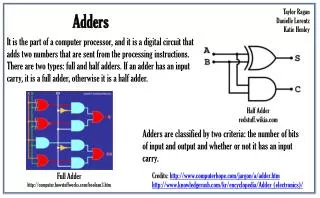
Floating-Point Add • Algorithm: Why 50-60 logic levels? • Sub-Modules: List of sub-blocks. floating-point number: S-sign, E-exponent, F-mantissa • floating-point addition: • input: (Sa,Ea,Fa) & (Sb,Eb,Fb) • output: (S,E,F) such that:
Normalize sum (shift left) SWAP operands Add/Sub mantissas Align mantissa of smaller operand (shift right) Convert sum to sign & mag abs(negative sum) rounding decision INC according to rounding decision Compute sticky-bit (OR of bits shifted outside) RESULT FP-Add: naïve algorithm Pre-process: Add/Sub: Round:
focus: normalization shift Problem: • LZ= number of leading zeros • shift left by LZ positions unary example: X[1:4]=0010 A[1:4]=0011 • Use a priority encoder! • two types of priority encoders: • unary • binary binary example: X[1:4]=0010 Y[2:0]= 010
Unary PENC • input: X[1:n] • Output: A[1:n] • functionality: Simpler: Implementation: what is the best design? Delay = (log n) & Cost = (n).
X[1:n/2] X[1+n/2:n] U- PENC(n/2) OR-tree(n/2) U-PENC(n/2) n/2 1 n/2 OR(n/2) A[1:n/2] A[1+n/2:n] Unary PENC –divide & conquer share OR-tree slight reduction of cost linear fan-out logarithmic delay delay: O(log n) is optimal O(log n) even if fan-out considered cost: O(n log n) not optimal
Unary PENC - improve Parallel Prefix Computation (PPC) [FL,BK]!
delay = O(log n) cost = O(n) X[1] X[2] X[3] X[4] X[n-1] X[n] OR OR OR U-PENC (n/2) OR OR A[2] A[4] A[n] Unary PENC = PPC(OR) A[1] A[3] A[n-1]
X[1] X[2] X[3] X[4] X[n-1] X[n] OR OR OR U-PENC (n/2) OR OR A[1] A[2] A[3] A[4] A[n-1] A[n] PPC - properties Fan-out: Logarithmic fan-out can be decreased to constant (cost still O(n)). Layout: O(n log n) area. Same design as “Brent-Kung” adder. Applicable for every associative operator.
Binary PENC • input: X[1:n] (n=2^k) • Output: Y[k:0] • functionality: Relation to Unary PENC: Implementation: what is the best design? Delay = (log n) & Cost = (n).
Binary PENC –simple & optimal X[1:n] PPC (OR) A[1:n] delay(diff(n)) = constant delay(encoder(n)) = O(log n) diff(n) encoder(n) cost(diff(n)) = O(n) cost(encoder(n)) = O(n) Y[k:0]
Binary PENC –with adder tree X[1:n] PPC (OR) A[1:n] ADD-tree(n) • problem: • adder(k) in tree O(log k) delay per adder • total delay is O(log n log k). Y[k:0]
a3 c3 a2 c2 a1 c1 a0 c0 b3 b2 b1 b0 x3 x2 x1 x0 y3 y2 y1 y0 Redundant addition add columns in parallel using Full-Adders Partial compression or (3:2)-addition: delay is constant! Tree structure enables (n:2)-addition with O(log n) delay. (n:2)-addition used in fast multipliers
X[1:n] PPC (OR) FA-tree(n) 2:1-Adder Y[k:0] Binary PENC –O(log n) delay A[1:n] 2[k:0] Tree of Full-Adders: delay of each full-adder is constant depth is O(log n) output is carry-save number
Binary PENC –divide & conquer 1 2 n/2 n/2+1 n XL XR XL=00…0 YL[k-1]=1
X[1:n/2] X[1+n/2:n] k Bin-PENC(n/2) Bin-PENC(n/2) 1 k k YL YR k YL[k-1] delay=constant cost=O(log n) delay=constant cost=O(log n) MUX(k) +2(k-1) (Half Adder) Y[k:0] Binary PENC –divide & conquer fan-out=k incurs O(log log n) delay initial analysis: delay = O(log n) cost = O(n) bottom line: delay = O(log n log logn ) cost = O(n)
PENC - further issues back to FP-Adder: can we estimate LZ before subtracting? must pre-process to avoid “catastrophic cancellation”! method: partial compression (signed half-adders).
k a b Compound Adder a+ba+b+1 rounding decision MUX RESULT focus – adder Avoid INC after rounding decision by pre-computing increment.
Define: PPC Adder [FL,BK] • computes carry bits C[n:1] • sum bits satisfy: S[i]=XOR(A[i],B[i],C[i]). • computation of carry bits C[n:1]. example: A[3:0]=0100 B[3:0]=1110 [3:0]=pgpk C[4:1]=1100 claim:
how to compute the event: define an operator : {k,p,g} {k,p,g} {k,p,g} as follows: g x = g p x = p k x = k claim: PPC adder (cont.) compute [i] using PPC with -gates! claim: is associative. definition: [i] = [i] … [0].
a+b+1 = (a+0.5)+(b+0.5) Therefore, Compound Adder [T] how to compute a+b & a+b+1? • use 2 separate adders • understand PPC adder recall: [i] = [i] … [0]. Now, for a+b+1: ’[i] = [i] … [0] g.
Conclusion • faster modules require clever designs • starting point: gate count (for delay & cost) • Must take fan-out & layout into account • lots of methods: • divide & conquer • parallel prefix computation • redundant arithmetic