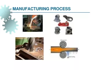
Manufacturing Process
Manufacturing Process. What is a Semiconductor?. polycrystalline amorphous crystalline. Low resistivity => “conductor” High resistivity => “insulator” Intermediate resistivity => “semiconductor” conductivity lies between that of conductors and insulators

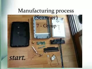
Manufacturing Process
E N D
Presentation Transcript
ManufacturingProcess EE141
What is a Semiconductor? polycrystalline amorphous crystalline • Low resistivity => “conductor” • High resistivity => “insulator” • Intermediate resistivity => “semiconductor” • conductivity lies between that of conductors and insulators • generally crystalline in structure for IC devices • In recent years, however, non-crystalline semiconductors have become commercially very important EE141
Semiconductor Materials Phosphorus (P) Gallium (Ga) EE141
Silicon Si has four valence electrons. Therefore, it can form covalent bonds with four of its nearest neighbors. When temperature goes up, electrons can become free to move about the Si lattice. EE141
Doping (N type) Notation: n = conduction electron concentration Si can be “doped” with other elements to change its electrical properties. For example, if Si is doped with phosphorus (P), each P atom can contribute a conduction electron, so that the Si lattice has more electrons than holes, i.e. it becomes “N type”: EE141
Doping (P type) Notation: p = hole concentration If Si is doped with Boron (B), each B atom can contribute a hole, so that the Si lattice has more holes than electrons, i.e. it becomes “P type”: EE141
CMOS Process EE141
A Modern CMOS Process Dual-Well Trench-Isolated CMOS Process EE141
Circuit Under Design EE141
Its Layout View EE141
The Manufacturing Process For a great tour through the IC manufacturing process and its different steps, check http://www.fullman.com/semiconductors/semiconductors.html EE141
Patterning of SiO2 Chemical or plasma etch Si-substrate Hardened resist SiO 2 (a) Silicon base material Si-substrate Photoresist SiO 2 (d) After development and etching of resist, chemical or plasma etch of SiO 2 Si-substrate Hardened resist (b) After oxidation and deposition SiO of negative photoresist 2 Si-substrate UV-light Patterned (e) After etching optical mask Exposed resist SiO 2 Si-substrate Si-substrate (f) Final result after removal of resist (c) Stepper exposure EE141
Photo-Lithographic Process optical mask oxidation photoresist photoresist coating removal (ashing) stepper exposure Typical operations in a single photolithographic cycle (from [Fullman]). photoresist development acid etch process spin, rinse, dry step EE141
Define active areas Etch and fill trenches Implant well regions Deposit and pattern polysilicon layer Implant source and drain regions and substrate contacts Create contact and via windows Deposit and pattern metal layers CMOS Process at a Glance EE141
p-epi (a) Base material: p+ substrate with p-epi layer + p Si N 3 4 SiO (b) After deposition of gate-oxide and 2 p-epi sacrificial nitride (acts as a buffer layer) + p (c) After plasma etch of insulating trenches using the inverse of the active area mask p + CMOS Process Walk-Through EE141
SiO 2 (d) After trench filling, CMP planarization, and removal of sacrificial nitride n (e) After n-well and V adjust implants Tp p (f) After p-well and V adjust implants Tn CMOS Process Walk-Through EE141
poly(silicon) (g) After polysilicon deposition and etch n + + p (h) After n + source/drain and p + source/drain implants. These steps also dope the polysilicon. SiO 2 (i) After deposition of SiO 2 insulator and contact hole etch. CMOS Process Walk-Through EE141
Al (j) After deposition and patterning of first Al layer. Al SiO 2 (k) After deposition of SiO 2 insulator, etching of via’s, deposition and patterning of second layer of Al. CMOS Process Walk-Through EE141
Advanced Metallization EE141
Advanced Metallization EE141
Implantation • Diffusion implantation: • The wafers are placed in a quartz tube embedded in a heated furnace. • A gas containing the dopant is introduced in the tube. The high temperatures of the furnace, typically 900 to 1100 °C, cause the dopants to diffuse into the exposed surface both vertically and horizontally. • Ion implantation: • Dopants are introduced as ions into the material. • The ion implantation system directs and sweeps a beam of purified ions over the semiconductor surface. • The acceleration of the ions determines how deep they will penetrate the material, while the beam current and the exposure time determine the dosage. • The ion implantation method allows for an independent control of depth and dosage. EE141
Deposition • Oxidation: • The wafer is exposed to a mixture of high-purity oxygen and hydrogen at approximately 1000°C. • The oxide is used as an insulation layer and also forms transistor gates. • Chemical vapor deposition (CVD): • CVD uses a gas-phase reaction with energy supplied by heat at around 850°C. • silicon nitride (Si3N4) ,Polysilicon, • Sputtering: • The aluminum is evaporated in a vacuum, with the heat for the evaporation delivered by electron-beam or ion-beam bombarding. EE141
Etching • Wet etching: • It uses many types of acid, base and caustic solutions to remove a material. • For instance, hydrofluoric acid buffered with ammonium fluoride is typically used to etch SiO2. • Dry or plasma etching: • A wafer is placed into the etch tool's processing chamber and given a negative electrical charge. • The chamber is heated to 100°C and brought to a vacuum level of 7.5 Pa, • It then filled with a positively charged plasma (usually a mix of nitrogen, chlorine and boron trichloride). • The opposing electrical charges cause the rapidly moving plasma molecules to align themselves in a vertical direction, forming a microscopic chemical and physical “sandblasting” action which removes the exposed material. • It creates patterns with sharp vertical contours. EE141