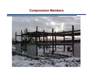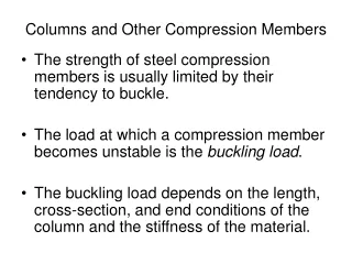
Compression Members
Compression Members. Compression Members. Compression members are susceptible to BUCKLING BUCKLING – Loss of stability Axial loads cause lateral deformations (bending-like deformations). P is applied slowly P increases Member becomes unstable - buckles. Column Theory.


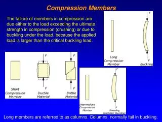
Compression Members
E N D
Presentation Transcript
Compression Members • Compression members are susceptible to BUCKLING • BUCKLING – Loss of stability • Axial loads cause lateral deformations (bending-like deformations) P is applied slowly P increases Member becomes unstable - buckles
Column Theory Axial force that causes Buckling is called Critical Load and is associated to the column strength • Pcr depends on • Length of member • Material Properties • Section Properties
P P y z Column Theory - Euler Elastic Buckling Governing Equation Solution Apply Boundary Conditions
Elastic Buckling Column Theory - Euler Buckling
Assumptions • Column is perfectly straight • The load is axial, with no eccentricity • The column is pinned at both ends No Moments Need to account for other boundary conditions
Other Boundary Conditions Free to rotate and translate Fixed on top Free to rotate Fixed on bottom Fixed on bottom Fixed on bottom
Other Boundary Conditions In general K: Effective Length Factor LRFD Commentary Table C-C2.2 p 16.1-240
Example I A W12x50 is used as a column to support a compressive load of 145 kips. The length is 20 ft and the ends are pinned. Without regard to LRFD or ASD investigate the stability of the column For a W12x50 OK – Column is Stable
Example I A W12x50 is used as a column to support a compressive load of 145 kips. The length is 20 ft the bottom is fixed and the top is free. Without regard to LRFD or ASD investigate the stability of the column For a W12x50 NG – Column is Unstable
AISC Requirements CHAPTER E pp 16.1-32 Nominal Compressive Strength AISC Eqtn E3-1
AISC Requirements LRFD
AISC Requirements ASD – Allowable Stress
To compute Fcr – ELASTIC BUCKLING Recall Assumptions
Assumptions • Column is perfectly straight • The load is axial, with no eccentricity • The column is pinned at both ends
To compute Fcr – ELASTIC BUCKLING Accounts for Imperfections
Alternatively Inelastic Buckling
Example A W14x74 of A992 steel has a length of 20 feet and pinned ends. Compute the design strength for LRFD and the allowable compressive strength for ASD Slenderness Ratio
Example LRFD ASD
Homework 4.3-1 4.3-4 4.3-6