Bridges and LAN Switches
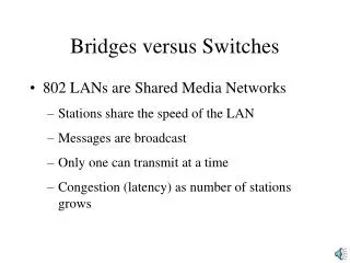
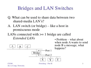
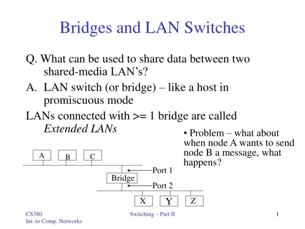
Bridges and LAN Switches. Q. What can be used to share data between two shared-media LAN’s? LAN switch (or bridge) – like a host in promiscuous mode LANs connected with >= 1 bridge are called Extended LANs. Problem – what about when node A wants to send node B a message, what happens?. A.

Bridges and LAN Switches
E N D
Presentation Transcript
Bridges and LAN Switches Q. What can be used to share data between two shared-media LAN’s? • LAN switch (or bridge) – like a host in promiscuous mode LANs connected with >= 1 bridge are called Extended LANs • Problem – what about when node A wants to send node B a message, what happens? A C B Port 1 Bridge Port 2 X Z Y Switching – Part II
Learning Bridges • Do not forward when unnecessary • Maintain forwarding Host Port A 1 B 1 C 1 X 2 Y 2 X 2 A B C Port 1 Bridge Port 2 X Z Y • Learn table entries based on source address • Table is an optimization; need not be complete • Always forward broadcast frames Switching – Part II
Spanning Tree Algorithm • Problem: loops • Bridges run a distributed • spanning tree algorithm • - select which bridges actively • forward • - developed by Radia Perlman • - now IEEE 802.1 specification Switching – Part II
What is a Spanning Tree? • The problem: • Tree - is connected graph with no cycles. • A Spanning Tree of G is a tree which contains all vertices • in G. • Example: Given a graph G • Is G a Spanning Tree? • YesNo • Note: Connected graph with n vertices and exactly n – 1 edges is Spanning Tree. Switching – Part II
Spanning Tree Example • Example: • G: 1 2 3 7 6 4 5 8 Switching – Part II
Centralized Spanning Tree Algorithm 1 #1 7 #7 2 3 #2 #6 5 4 6 #4 #3 #5 8 • DFS (Depth First Search) Switching – Part II
Centralized Spanning Tree Algorithm 1 #1 #2 2 3 #3 #4 #5 #6 4 5 6 7 #7 8 • BFS (Breadth First Search) Switching – Part II
Distributed Spanning Tree Algorithm - Overview • Each bridge has unique id(e.g., B1, B2 ,B3 ) • Select bridge with smallest id as root • Select bridge on each LAN closest to root as the designated bridge(use id to break ties) Switching – Part II
Distributed Spanning Tree Algorithm - Detail • Bridges exchange configuration messages • id for bridge sending the message • id for what the sending bridge believes to be root bridge • distance(hops) from sending bridge to root bridge • Each bridge records current “best” configuration message for each port • Initially, each bridge believes it is the root and sends messages out on all its ports(distance to root = 0) • When learn not root, stop generating configuration messages • in steady state, only root generates configuration messages • When learn not designated bridge, stop forwarding config messages(disconnected) • in steady state, only designated bridges forward config messages • Root continues to periodically send config messages • If any bridge does not receive config message after a period of time, it starts generating config messages claiming to be the root Switching – Part II
Distributed Spanning Tree Algorithm - Overview • Ports which are not selected (disconnected) by the Distributed Spanning Tree Algorithm × × × × × Switching – Part II
Limitations of Bridges • Do not scale • Spanning tree algorithm does not scale (no hierarchy) • Broadcast does not scale(congestion) • Do not accommodate heterogeneity (Ethernet-to-Ethernet, but not others such as ATM) • Caution: beware of transparency • If a host is configured for single-LAN use, unexpected results can come about • Bridges might drop frames(congestion) • Latency differences • Frame reordering Switching – Part II
Asynchronous Transfer Mode(ATM) • Connection-oriented packet-switched network (virtual circuits) • Used in both WAN and LAN settings • Signaling(connection setup) Protocol: Q.2931 • Packets are called cells • 5-byte header + 48-byte payload(fixed length) • Commonly transmitted over SONET • Other physical layers possible Switching – Part II
Big vs Small Packets • Small improves Queue behavior • Finger-grained pre-emption point for scheduling link • Maximum packet = 4 KB • Link speed = 100Mbps • Transmission time = 4096 8/100=327.68s • High priority packet may sit in the queue 327.68 s • In contrast, 53 8/100 = 4.24 s for ATM • Near cut-through behavior • Two 4KB packets arrive at same time • Link idle for 327.68 s while both arrive • At end of 327.68 s, still have 8KB to transmit • In contrast, can transmit first cell after 4.24 s • At end of 327.68 s, just over 4KB left in queue Switching – Part II
Variable vs Fixed-Length Packets • No Optimal length • If small: high header-to-data overhead • If large: low utilization for small messages • Fixed-Length Easier to Switch in Hardware • Simpler • Enables parallelism • Telephone company supported! Switching – Part II
Big vs Small Packets • Small improves Latency(for voice) • Voice digitally encoded at 64Kbps (8-bit samples at 8 KHz) • Need full cell’s worth of samples before sending cell • Example: 1000-byte cells implies 125ms per cell(too long) • Smaller latency implies no need for echo cancellors • ATM Compromise: 48 bytes = (32 + 64) / 2 • Excellent case study of standardization • U.S. wanted 64-byte cell & Europe wanted 32-byte cell Switching – Part II
Cell Format • User-Network Interface(UNI) • Host-to-switch format • GFC: Generic Flow Control – arbitrate access to link • VCI:Virtual Circuit Identifier • VPI:Virtual Path Identifier • Type:management, congestion control, AAL5(later0 • CLP:Cell Loss Priority • HEC:Header Error Check(CRC-8) • Network-Network Interface(NNI) – between telcos • Switch-to-switch format • GFC becomes part of VPI field 4 16 3 1 8 8 384 (48 bytes) GFC VPI VCI Type CLP HEC (CRC-8) Payload Switching – Part II
Segmentation and Reassembly (SAR) • Really Fragmentation and Reassembly • High level protocols hand packets down to lower-level protocols with headers added • In ATM, Packets often too large • Packets are split up, sent on, and reassembled • Protocol layer added - ATM adaptation Layer(AAL) • Sits between ATM and IP • Contains information needed by receiver for reassembly Switching – Part II
Segmentation and Reassembly • Four possible ATM Adaptation Layers(AAL) • AAL 1 and 2 designed for applications that need guaranteed rate(e.g., voice, video) • AAL 3 / 4 designed for packet data(connectionless) • AAL 5 is an alternative standard for packet data AAL AAL … … ATM ATM Switching – Part II